
Interactive on line code inspection process and tool

a technology of interactivity and code inspection, applied in the direction of instruments, data processing applications, computing, etc., can solve the problems of insufficient use of program developers' time in preparing code inspection minutes

Inactive Publication Date: 2001-08-14
RPX CLEARINGHOUSE
View PDF14 Cites 179 Cited by
  • Summary
  • Abstract
  • Description
  • Claims
  • Application Information

AI Technical Summary

Problems solved by technology

After each code inspection meeting, the developers attempt to modify or re-write any code lines for which they have responsibility, and which have been identified as being problematic or capable of improvement at the code inspection meeting.
Although code inspection meetings are an essential part of building a program, there are several problems associated with such meetings.
Firstly, good experienced program developers are scarce, and their time is valuable.
Having three or four program developers spending time photocopying code, and having a program developer preparing minutes of a code inspection meeting is not an optimum use of their time.
However, preparing material to bring along to a code inspection meeting is a skilled task, and therefore needs to be carried out by developers and is not easily delegated.
Secondly, preparation of minutes of the meeting introduces a delay into product development, since programmers may not address problems identified at the code of inspection meeting until the typed up minutes of the meeting are available.
Fourthly, there is the problem that the rate at which lines of code can be inspected is relatively low.
However, such a code inspection overhead is unrealistic, since the necessary resource of developer time is unavailable, and if available, would be better utilized on other tasks.
Further, it may be that some lines of code require more than one code inspection.

Method used


Image

  • Interactive on line code inspection process and tool
  • Interactive on line code inspection process and tool
  • Interactive on line code inspection process and tool

Examples


Embodiment Construction

There will now be described by way of example the best mode contemplated by the inventors for carrying out the invention. In the following description numerous specific details are set forth in order to provide a thorough understanding of the present invention. It will be apparent however, to one skilled in the art, that the present invention may be practiced without limitation to these specific details. In other instances, well known methods and structures have not been described in detail so as not to unnecessarily obscure the present invention.

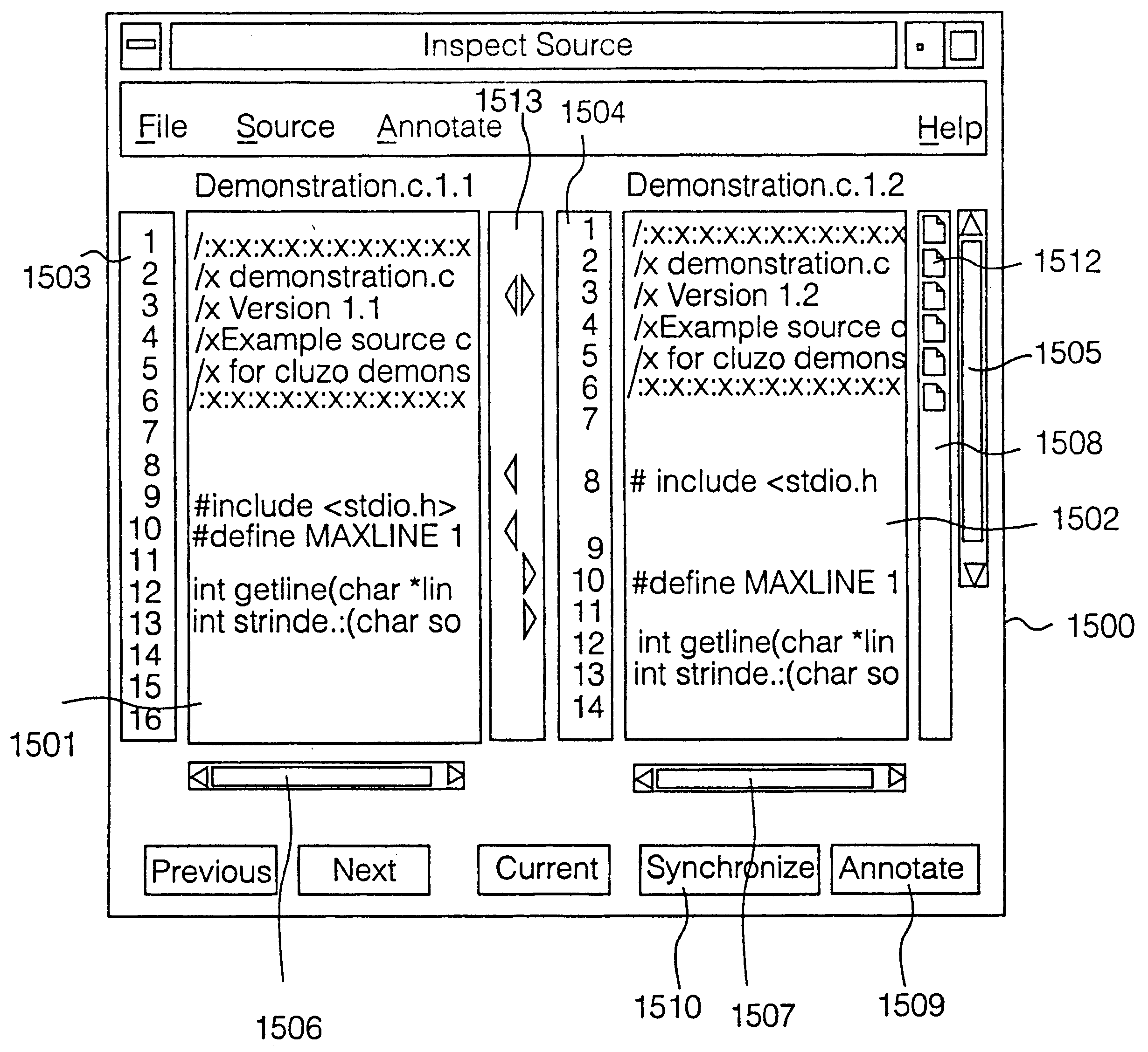
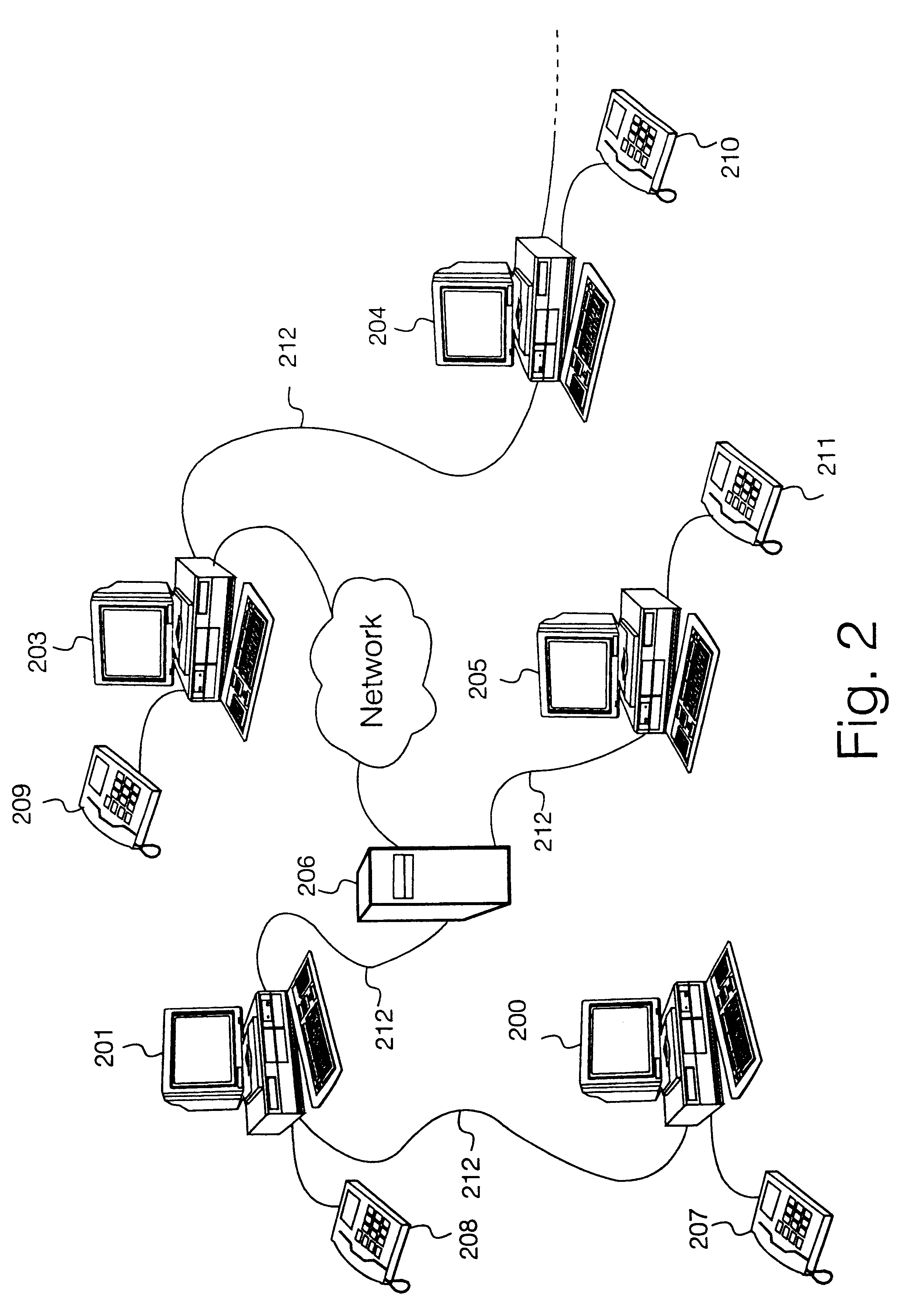
Referring to FIG. 2 herein, there is illustrated in general view, a code inspection tool according to a first specific implementation of the present invention. The code inspection tool comprises a plurality of computing and data processing physical resources (200-206), including a plurality of processors; a plurality of memory areas; and a plurality of graphical user interfaces, each graphical user interface comprising a visual display devi...


PUM


Abstract

A code inspection tool comprises a plurality of physical computing resources connected by a network facility, eg an LAN, intranet or internet, and a voice conferencing communications facility. The code inspection tool interfaces with a known configuration management system to load a quantity of original source code. A group of developers use a plurality of graphical user interfaces to inspect the code. All graphical user interfaces log into display views generated on a main graphical user interface, which is operated by a human controller of a code inspection session. The code inspection tool comprises means for allowing developers to compile annotation data and forward the annotation data from their respective graphical user interfaces to a centralized data store. Internal algorithms of the code inspection tool compile markers relating the annotation data files to individual lines of source code. During a code inspection session, all developers view a same display, which sets out original source code, side by side with new source code on a line by line basis, matching the line numbers of the original source code with those of the new source code. Changes to the original source code and new source code are visually identified by automatic generation of icons next to the appropriate source code lines on the display. Annotations to the source code lines are indicated by further icons next to the appropriate lines. The tool automatically generates data describing statistics of a code inspection process, for example number of lines inspected, during of a code inspection session, proportion of original and new code lines inspected. Code inspection reports may be generated in a variety of formats, eg plain text or HTML, and automatically distributed to individual developers over the networked facility.

Description

The present invention relates to a method and apparatus for inspection of computer code.BACKGROUND TO THE INVENTIONConventional modem communication systems rely heavily on physical resources which are controlled by data processing devices, eg, switch fabrics, routers, frequency channel assignment apparatus, networked personal computers, network management systems and the like. Data processing devices typically operate in accordance with the known Von Neumann methods, in which a large number of logic elements eg, bi-stable devices, transistors or the like sequentially switch between states under control of (typically) electronic signals. Large collections of such signals comprise a know computer program. At a higher level, the individual signals which control individual logic devices are assembled from a set of instructions written in a known computer language. Such instructions are generically referred to as code. A conventional computer program may contain hundreds of thousands, to...

Claims


Application Information

Patent Timeline
IPC IPC(8): G06F3/033G06F3/048
CPCG06F3/0483Y10S715/971
Inventor HUGHES, GERARD JOHN
Owner RPX CLEARINGHOUSE
Learn More