
Ink cartridge and remaining ink volume detection method

a technology of ink cartridges and ink cartridges, applied in printing and other directions, can solve the problems of inefficiency operation, inability to achieve operation, and inability to apply seals to the case openings, and achieve the effect of simple operation and easy ink filling

Inactive Publication Date: 2001-08-07
BROTHER KOGYO KK
View PDF16 Cites 133 Cited by
  • Summary
  • Abstract
  • Description
  • Claims
  • Application Information

AI Technical Summary

Benefits of technology

The present invention has been devised for the purpose of resolving the problems with the prior art described in the foregoing. A first object thereof is to provide an ink cartridge wherewith bringing a filling apparatus and a pressure reduction apparatus close to the cartridge package for ink filling is rendered easy, and the operation of applying seals to the case openings is made simple.
Based on this method, capillary action is induced at the ridge part extending vertically up and down and formed by the intersection of at least two inner surfaces of the ink chamber, whereby ink adhering to the inner surfaces of the ink chamber moves immediately, in conjunction with the fall in the ink liquid level, to a point proximate to that ink liquid level, wherefore there will be no erroneous detections of the presence or absence of ink at the detection site, and the remaining ink quantity in the ink chamber can be detected precisely.

Problems solved by technology

When air bubbles are mixed in with the ink liquid that is supplied from the ink cartridge, however, this has an adverse effect on the ejection of ink from the nozzles in the recording head.
Not only does this require a long length of tape, but, when the sealing tape is applied using a roller mechanism, the operation cannot be accomplished from one side of the case, so the sealing tape must be pulled around the case from the upper surface to the lower surface while rotating the case, thus involving an inefficient operation.
If the ink filling hole is wet with ink, however, heat welding cannot be adequately performed.
When more heat is applied to avoid this, a problem arises in that the ink supply hole is deformed so that it cannot be properly connected to the recording head.
During the ink filling operation, moreover, when the interior of the case is placed under reduced pressure by the pressure reduction apparatus, the entire case is sometimes deformed, whereupon the case cannot be efficiently filled with ink.
However, because the liquid level tends to shake and fluctuate because the ink cartridge is mounted on a carriage that moves in a sweeping motion in the width direction of the recording medium, erroneous detections often to occur.
This measure, however, requires the case structure to be complex.
With this method, however, it is difficult to detect the remaining ink quantity accurately because the presence or absence of ink in the porous material differs from location to location therein.
Accordingly, in cases where the detection site for a sensor is located near the center of the cartridge wall surface, even when the ink liquid level falls, so that there is little actual remaining ink quantity, that fact cannot be detected, wherefore erroneous detections occur, which is a problem.
Thus, when there are slight irregularities in the distance between the reflected light sensor and the detection site, or in the attachment position or angle of the reflected light sensor relative to the detection site, the light receiving element cannot properly detect the reflected light, so that the remaining ink quantity inside the ink cartridge cannot be detected or the remaining ink quantity detection precision sharply declines.
If the case is transparent or semi-transparent, the case will become unsightly once ink penetrates into the atmosphere connection chamber.
If the ink plugs up the atmosphere connection hole, that will impair the supply of ink to the recording head.
With such a structure as this, when air bubbles intrude into the second chamber from the first chamber, and those air bubbles are drawn to the recording head from the second chamber, there is a danger that the recording head will become incapable of ink ejection due to the air bubbles.
Supposing that a substantially rectangular ink cartridge is contained in a packaging bag, and that the packaging bag adheres tightly to the cartridge, outside air that gradually penetrates through the packaging bag will relatively quickly fill the slight gap between the packaging bag and the ink cartridge, making it difficult to maintain the reduced pressure condition for any extended period of time.
When separate components are inserted inside the packaging bag, however, the number of manufacturing processes increases, costs rise, and the exterior shape of the packaging bag becomes large, which is undesirable in the interest of smaller size.

Method used


Image

  • Ink cartridge and remaining ink volume detection method
  • Ink cartridge and remaining ink volume detection method
  • Ink cartridge and remaining ink volume detection method

Examples


Embodiment Construction

A specific embodiment of the present invention is now described with reference to the drawings.

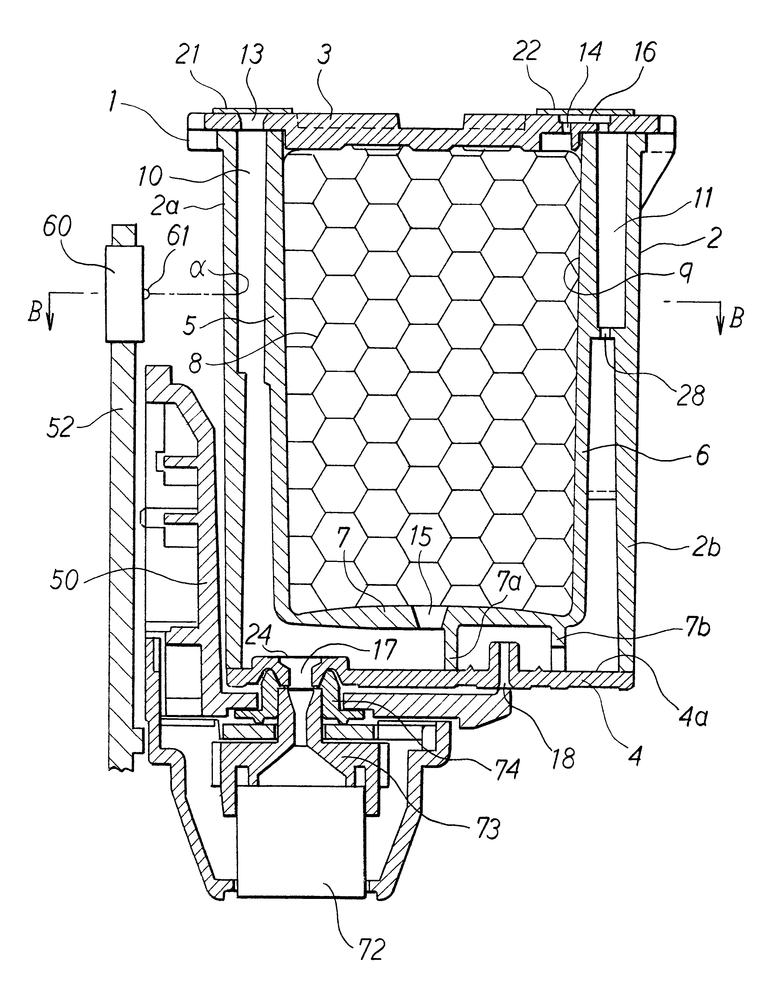
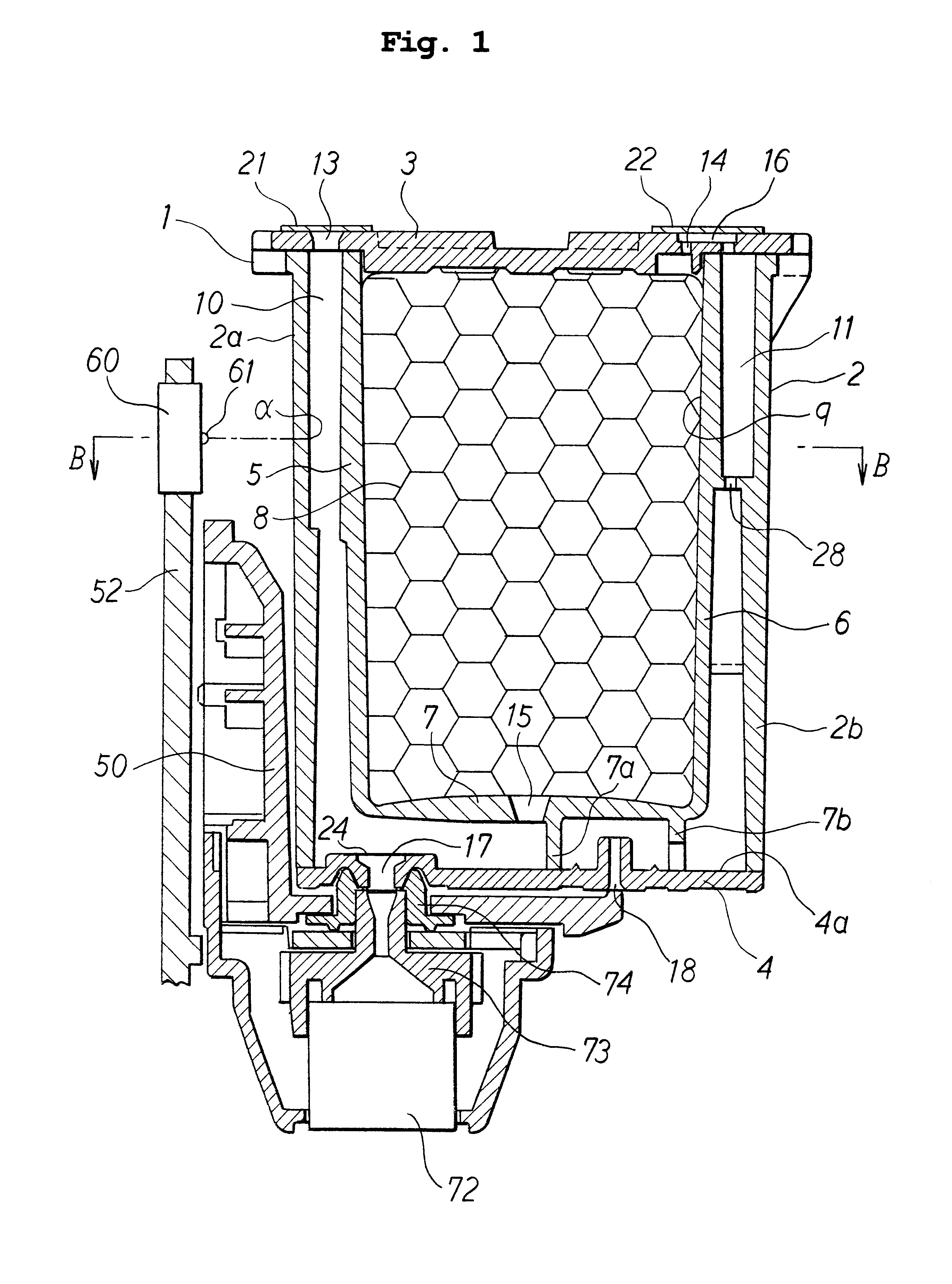
FIG. 1 is a diagram of the ink cartridge according to this embodiment, showing it connected to a recording head. A head holder 50 for supporting the recording head 72 is mounted on a carriage 52 which moves so as to sweep across a recording medium. In this holder 50 is loaded the ink cartridge 1 so that it can be detached. An ink supply hole 17 made in the bottom surface of the ink cartridge 1 fits into a joint member 74 on the head holder 50 side, and ink is distributed through a manifold member 73 to many ink ejection channels in the recording head 72. The recording head 72 ejects ink from the ink ejection channels by the action of actuators consisting of piezoelectric elements or heating elements.

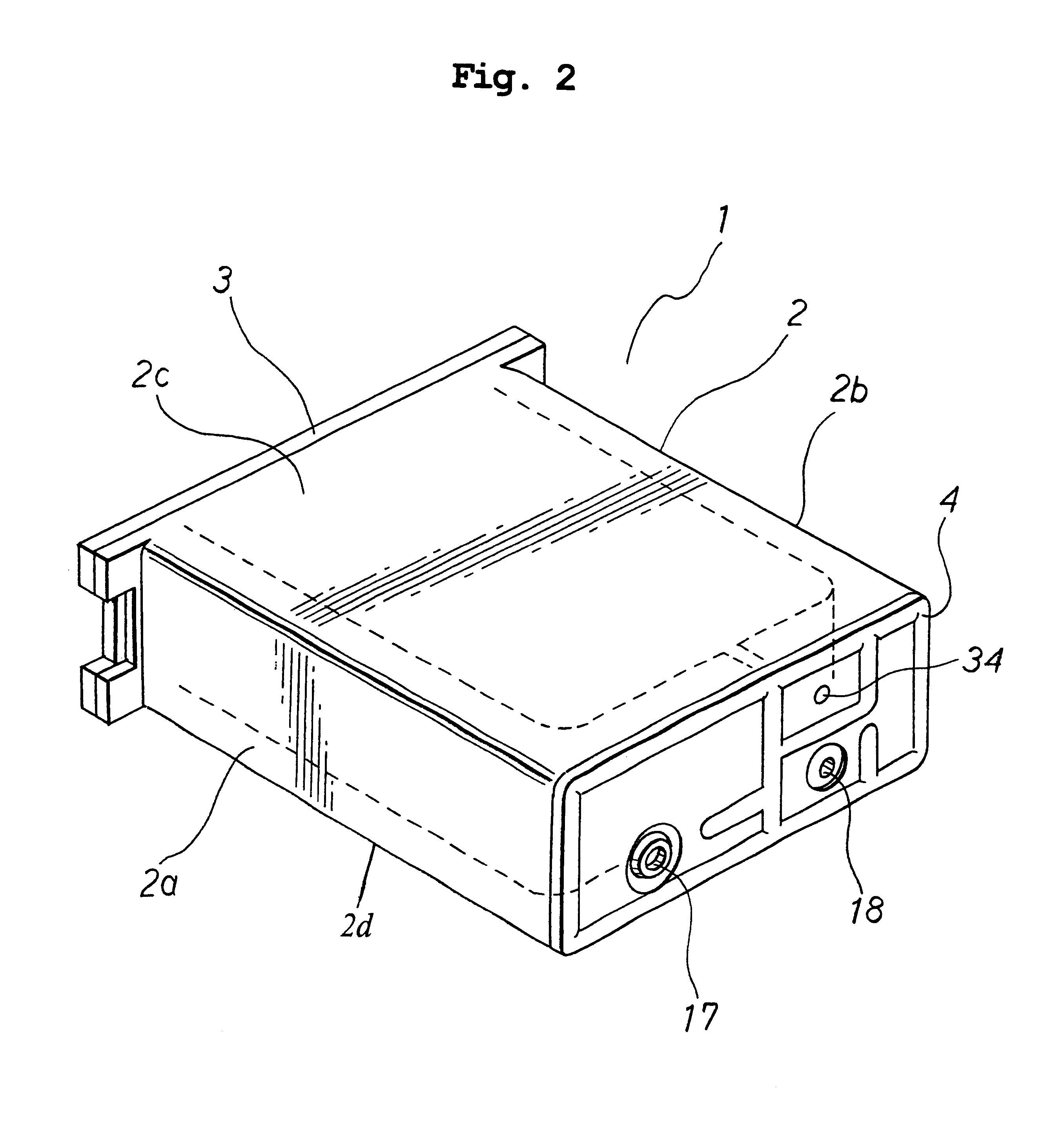
The ink cartridge 1 according to this embodiment comprises a case 2 made in a rectangular shape from a transparent or semi-transparent resin material, and upper and lower cover members 3 and 4....


PUM


Abstract

An ink cartridge has a first partitioning wall 5 and a third partitioning wall 7 for dividing the inside of a case 2 into a first ink chamber 9 and a second ink chamber 10, and a second partitioning wall 6 for demarcating an atmosphere connection chamber 11. In an upper case cover 3 are formed an ink filling hole 13 communicating with the second ink chamber 10 and a pressure reduction hole 14 communicating with the atmosphere connection chamber 11. Therefore, when ink filling is being done, the filling apparatus and the pressure reduction apparatus need only be brought to bear from one side of the upper case cover, resulting in improved work efficiency. Ink filling can be performed efficiently because the ink successively passes to the second ink chamber 10 and the first ink chamber 9. After ink filling, the ink filling hole 13 and the pressure reduction hole 14 can easily be sealed off with sealing material. An ink cartridge is thus provided that can be easily assembled at low cost.

Description

BACKGROUND OF THE INVENTION1. Field of the InventionThis invention relates to an ink cartridge for holding ink that is supplied to a recording head, that is removably attached to recording heads used in image forming apparatuses, and to an ink volume detection method for the ink cartridge.2. Description of the Related ArtConventionally, image forming apparatuses such as ink jet printers eject ink droplets from nozzles in a recording head mounted on a carriage, thereby recording images on recording media. The ejection of the ink droplets is accomplished by driving actuators such as electric-to-mechanical converter elements or electric-to-thermal converter elements positioned inside the recording head to generate pressure waves. The ink is supplied from an ink cartridge mounted on the recording head so that it can be easily removed and replaced. When air bubbles are mixed in with the ink liquid that is supplied from the ink cartridge, however, this has an adverse effect on the ejectio...

Claims


Application Information

Patent Timeline
IPC IPC(8): B41J2/175
CPCB41J2/17513B41J2/17566B41J2002/17573
Inventor SASAKI, TOYONORI
Owner BROTHER KOGYO KK
Learn More