
Vehicular lamp

a technology of vehicle lamps and lampshades, which is applied in the direction of fixed installation, transportation and packaging, lighting and heating equipment, etc., can solve the problems of increased lamp manufacturing costs, increased molding facilities, and increased processing steps

Inactive Publication Date: 2001-07-31
KOITO MFG CO LTD
View PDF7 Cites 11 Cited by
  • Summary
  • Abstract
  • Description
  • Claims
  • Application Information

AI Technical Summary

Benefits of technology

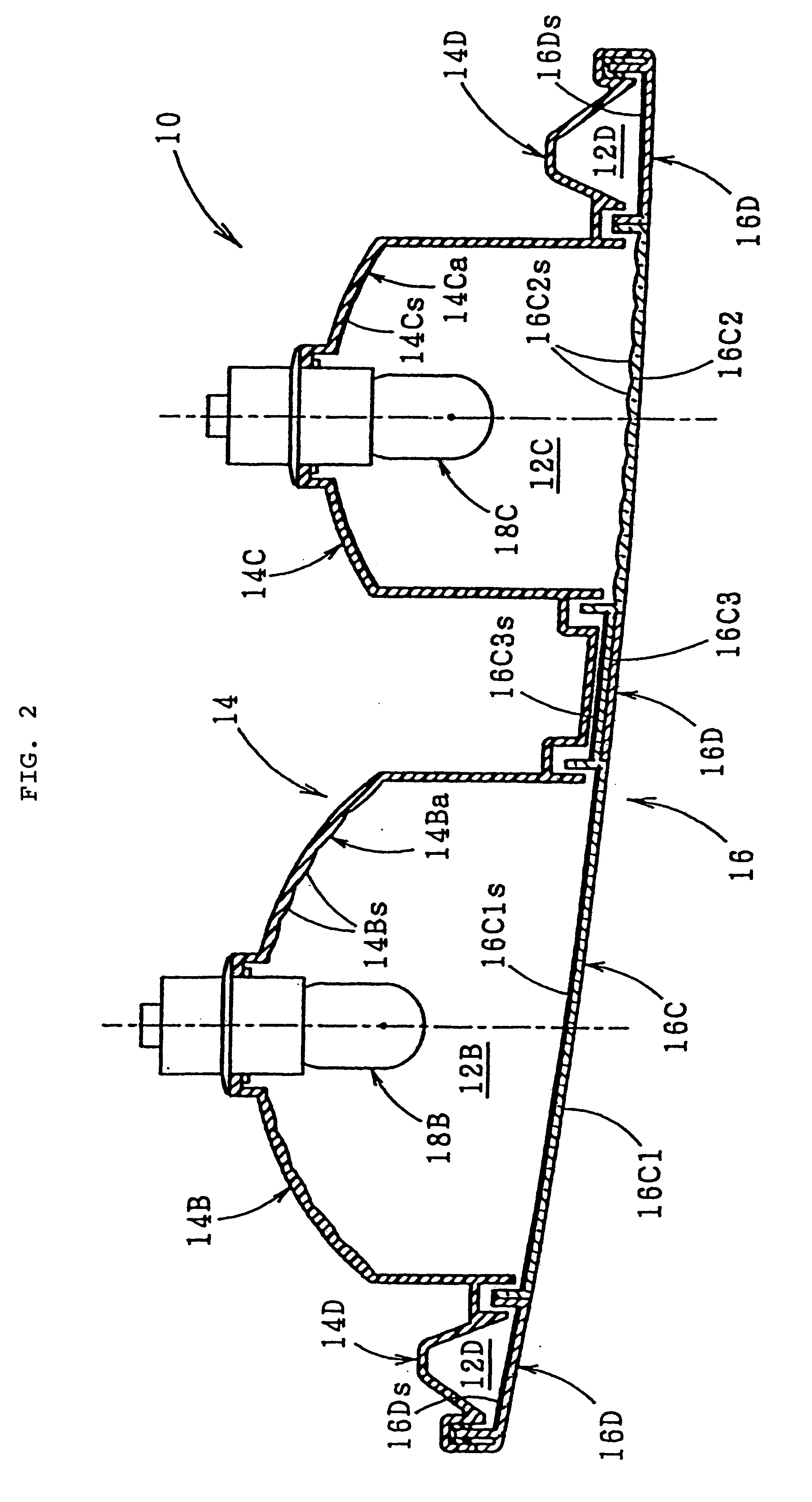
As seen from the above, the vehicular lamp according to the present invention is provided with the red color light emitting portion, the amber color light emitting portion and the clear light emitting portion, and these light emitting portions are surrounded by the dummy portion; and further, the front portion of either one of the two light emitting portions (the red color light emitting portion, for instance) is formed with a colored lens that has the same color (red, for instance) as the color of such the light emitting portions, and the front portion of the other one of the two light emitting portions (the amber color light emitting portion, for instance) and the front portion of the clear light emitting portion are formed with the clear lens. Further, the front portion of the dummy portion is formed with the dummy lens that has a color different from these colors (red and amber). Therefore, the front lens, that includes those front portions, for the lamp can be manufactured using an existing three-color molding. Also, in the above structure, the predetermined optical member, except for the clear lens, of the other one of the two light emitting portions (the amber color light emitting portion, for instance) functions as a color developing member which develops the light of the same color (amber) as the luminescent color of the amber color light emitting portion when it is lighted. Accordingly, even the front portion of the other one of the two light emitting portions (the amber color light emitting portion) is formed clear with the clear lens, the other one of the two light emitting portions (the amber color light emitting portion) emits amber light, thus fulfilling the intended lamp function.
Accordingly, the vehicular lamp of the present invention, that is provided with the red color light emitting portion, the amber color light emitting portion and the clear light emitting portion which are surrounded by the dummy portion, can be manufactured at lower costs.

Problems solved by technology

A three-color molding is generally used when the front lenses for rear combination lamps are molded; however, when such front lenses are formed by a four-color molding, new molding facilities become necessary, and additional processing steps are required due to the addition of one color.
Thus, the lamp manufacturing costs tend to increase.

Method used


Image

  • Vehicular lamp
  • Vehicular lamp
  • Vehicular lamp

Examples


Embodiment Construction

Embodiments of the present invention will be described with reference to the accompanying drawings.

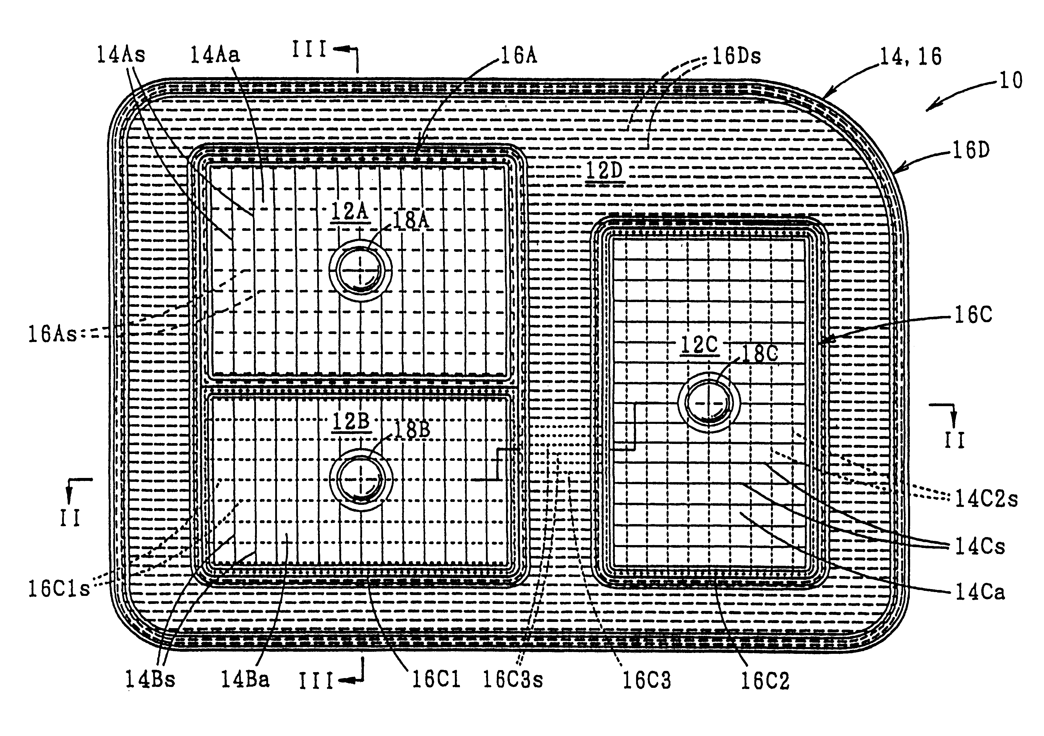
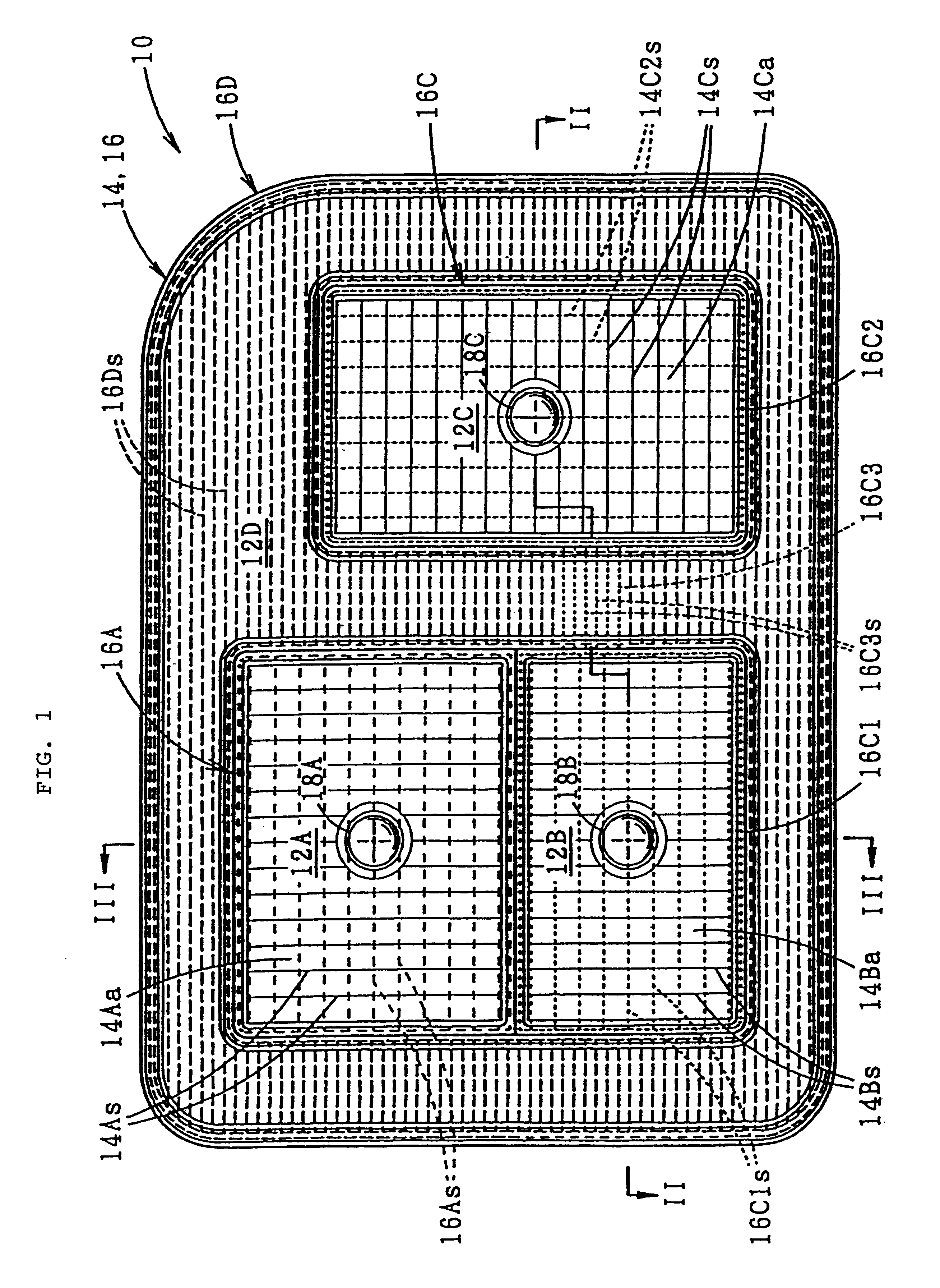
As shown in the drawings, the vehicular marker lamp 10 of the present invention is a combination lamp, and it has the functions of a tail and stop (red) lamp, a turn signal (amber) lamp and a backup (clear) lamp.

The combination lamp 10 comprises a vertically arranged light emitting portion that consists of a red color light emitting portion 12A for the tail and stop lamp and an amber color light emitting portion 12B for the turn signal lamp. A clear light emitting portion 12C for the backup lamp is also a part of this combination lamp 10, and it is provided next to or away from the light emitting portions 12A and 12B. These three light emitting portions 12A, 12B and 12C are surrounded by a dummy portion 12D that does not emit any light.

The three light emitting portions 12A, 12B and 12C and the dummy portion 12D make up a lamp body 14 and a front lens 16 installed in front of the lamp b...


PUM


Abstract

A vehicular lamp comprising a red color lens provided in front of a red color light emitting portion, clear lenses provided in front of an amber color light emitting portion and a clear light emitting portion, and a smoky color dummy lens provided in front of a dummy portion that surrounds these light emitting portions. An amber color bulb is used in the amber color light emitting portion and amber color paint is applied to the reflective surface of the reflector portion of the amber color light emitting portion. Thus, amber light is emitted when the amber color light emitting portion is lighted even though the amber color light emitting portion is covered by clear lenses; and the entire lamp chamber of the amber color light emitting portion looks uniformly luminous in an amber color despite the clear lens provided in front of the amber color light emitting portion.

Description

1. Field of the InventionThe present invention relates to a vehicular lamp that has a red color light emitting portion, an amber color light emitting portion and a clear light emitting portion which are surrounded by a dummy portion.2. Prior ArtA typical vehicular marker lamp such as a rear combination lamp comprises a red color light emitting portion, an amber color light emitting portion and a clear light emitting portion. The front portion of each one of these light emitting portions is formed with a lens that has the same color as the luminescent color of each one of the light emitting portions. In other words, the front portion of the red color light emitting portion is red, the front portion of the amber color light emitting portion is amber, and the front portion of the clear light emitting portion is clear or has no color. In some marker lamps, due to designing demands, the surrounding areas of these three light emitting portions are formed as a dummy portion, and this dummy...

Claims


Application Information

Patent Timeline
IPC IPC(8): B60Q1/26F21V9/08F21V9/00F21S8/10
CPCF21S48/2218B60Q1/2607F21S43/255
Inventor FUNADA, YASUAKI
Owner KOITO MFG CO LTD
Learn More