
Automated transaction machine with note storage reel

a note storage and transaction machine technology, applied in the field of automatic transaction machines, can solve the problems of inability to readily document the responsibility of theft and tampering, the inability to secure the secure, and the inability to secure the safe, so as to reduce the cost of production and operation, the effect of easy installation and removal

Inactive Publication Date: 2001-07-24
DIEBOLD NIXDORF
View PDF23 Cites 9 Cited by
  • Summary
  • Abstract
  • Description
  • Claims
  • Application Information

AI Technical Summary

Benefits of technology

Enables secure, cost-effective, and efficient currency note replenishment and dispensing without internal access, reducing security risks and operational costs, while allowing for easy integration with existing machines and enhanced user experience through promotional messaging.

Problems solved by technology

A drawback associated with the construction of such conventional automated transaction machines is that replenishing the sheet supplies requires opening the secure area of the machine.
This presents opportunities for theft and tampering.
This may present opportunities for pilferage for which responsibility cannot be readily documented.
However such containers are not failsafe and may still be subject to compromise by skilled thieves.
Sheet holding canisters may also be stolen in their entirety when in transit to and from machines.
The use of currency canisters is also expensive.
The use of such canisters adds to the cost of the automated transaction machines by requiring the inclusion of mechanisms that can open, close and work in conjunction with sheet containing canisters.
The handling and transport of canisters also adds to the cost of machine operation.
While the reduced capabilities of such machines results in a lower machine acquisition cost, the problems of handling sheets still exists.
This adds to the cost of machine operation.
However in many merchandise transaction environments the trustworthiness of the personnel may not be verifiable.
As a result the machine operator may not want to give their personnel access to the large amounts of cash which are available within the interior of an automated transaction machine.
Replenishing the currency supplies within such machines may be an activity limited to supervisory level personnel.
However, despite such precautions shortages and discrepancies can occur.
While such machines have the capability of having the note supplies replenished without accessing the interior of the machine, such machines are generally complex and expensive.
The installation of such a machine would generally not be cost justified in situations where relatively low cost, cash dispense only type machines are currently used.
Cash receiving and dispensing capability has generally not been provided in most self service and vending machines for several reasons.
First, cash dispensing and accepting mechanisms have in the past generally been expensive and would render such machines cost prohibitive to acquire and operate.
Second, such machines generally do not include the security features included in automated teller machines or cash dispensers, because the items generally dispensed by such machines are not readily disposed of for cash value.
Another reason such machines have not been provided with cash accepting and / or dispensing capability is that to do so would require the machine operators to incur the additional costs associated with cash handling previously discussed, that are often encountered in the use of operating ATMs and cash dispensers.
A further drawback has been that making cash acceptance and dispensing an integral part of such machines may limit their operation to selected hours and locations where greater security may be maintained.
Thus, while users may benefit from having machines such as motor fuel dispensing pumps and vending machines accept and receive cash, providing such machines with these capabilities has been cost prohibitive.

Method used


Image

  • Automated transaction machine with note storage reel
  • Automated transaction machine with note storage reel
  • Automated transaction machine with note storage reel

Examples


Embodiment Construction

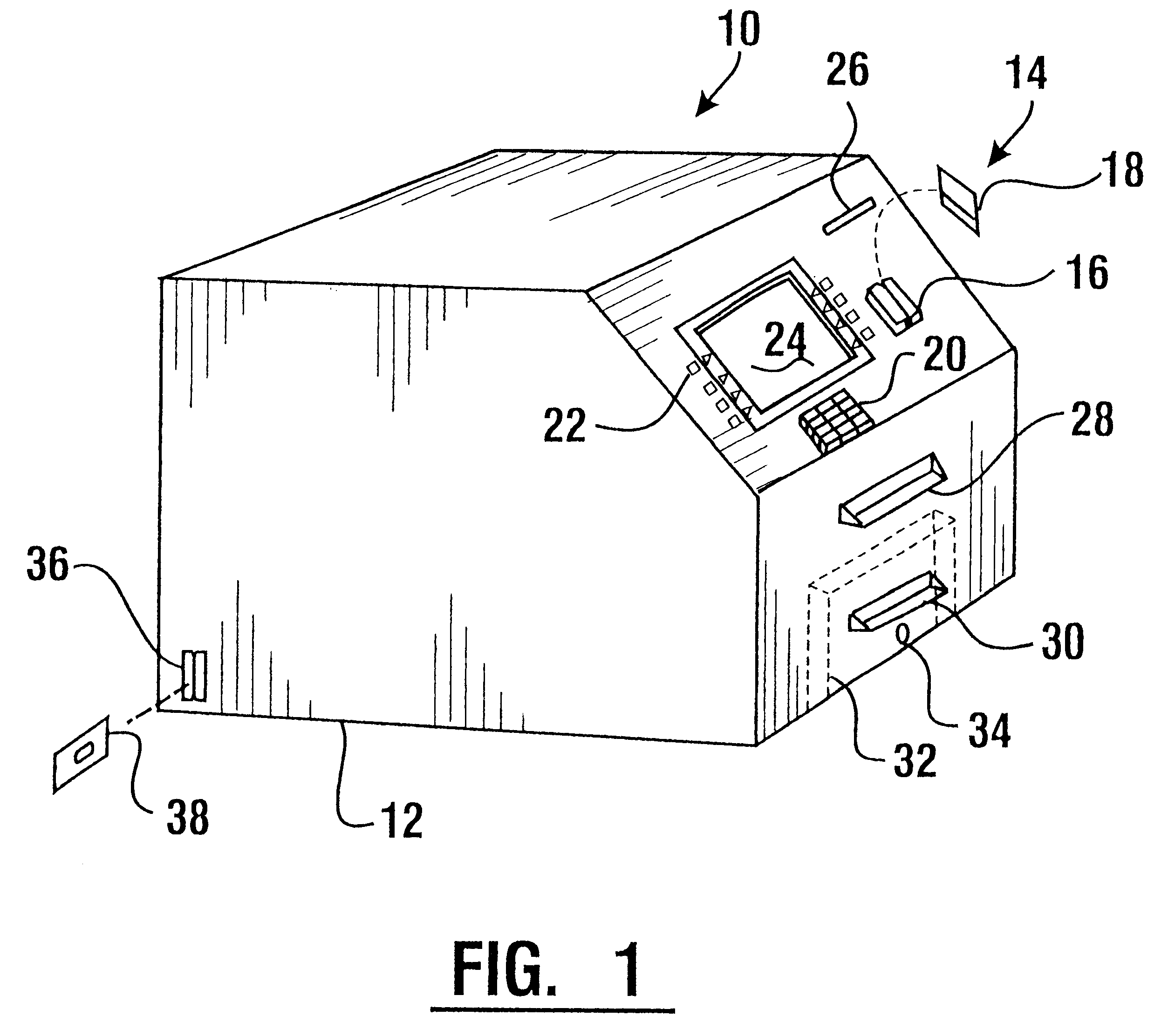
Referring now to the drawings and particularly FIG. 1 as shown therein an automated transaction machine of a first exemplary embodiment of the present invention generally indicated 10. Machine 10 is an automated teller machine whose primary functions are to dispense and receive currency notes. It should be understood however that other embodiments of the invention may be machines whose primary functions include conducting other types of transactions. These may include for example the dispense of motor fuel, the dispense of tickets, the dispense of vouchers, the dispense of gaming materials or other functions that a user may carry out using the machine.

Machine 10 includes a housing 12. As used herein housing 12 refers to the external enclosure of the machine as well as the internal structures which support components of the machine therein. A user interface generally indicated 14 is supported on the housing and is accessible by a user. In the embodiment shown the user interface inclu...


PUM

PropertyMeasurementUnit
angleaaaaaaaaaa
angleaaaaaaaaaa
timeaaaaaaaaaa

Abstract

An automated transaction machine (10) includes a note receiving and dispensing mechanism (77). The mechanism includes a storage reel (66), a take-up reel (68) and a flexible web (70) extending between the reels. A drag applying member (196; 208) may be used in operative connection with at least one of the reels. The note receiving and dispensing mechanism is housed within a note storage module (44). Notes are selectively passed into and out of the storage module to a passage area (92). The machine further includes a note inlet opening (30) and a note outlet opening (28). A note outlet transport (96) extends between the passage area and the note outlet opening. A note inlet transport (98) extends between the passage area and the note inlet opening. A note validator (58) extends adjacent to the note inlet transport for purposes of sensing the validity of notes inserted in the machine. The machine is selectively operative responsive to inputs to receive and deliver notes. The machine is further operative to enable replenishment of notes therein without accessing the interior of the housing.

Description

This invention relates to automated transaction machines. Specifically this invention relates to an automated transaction machine that dispenses notes to users and which has an internal note storage area which may be replenished without accessing the interior of the machine.Automated transaction machines are known in the prior art. A common type of automated transaction machine is an automated teller machine (ATM). ATMs have been developed which are capable of performing a variety of transactions including the dispensing of currency notes. Other types of transaction machines dispense notes and other types of sheets to users such as bank tellers, cashiers and other service providers. Other types of automated transaction machines dispense items such as tickets, travelers checks, scrip, vouchers or gaming materials. Automated transaction machines generally dispense such materials while assessing appropriate charges and credits to the respective accounts of the user, the machine owner a...

Claims


Application Information

Patent Timeline
Patent Type & Authority Patents(United States)
IPC IPC(8): G07D11/00G07F19/00G06FG07F5/00G07F7/04
CPCB65H29/006G06Q20/042G07F19/203G07D11/0057G07D11/0081G07F19/20G06Q20/1085B65H2301/4191B65H2701/1912G07D11/40G07D11/245
Inventor HANEY, SEANOWENS, MARKJUNKINS, ANDREWGRAEF, H. THOMAS
Owner DIEBOLD NIXDORF
Learn More