
Triangular hand massager

a hand massager and triangular technology, applied in the field of massage tools, can solve the problems of affecting the effect of the body, the corner or arris of the bottom side portion of the leg tends to bite into the body, and the legs are flat bottom side portions, etc., and achieves the effect of being easily and firmly held with minimal effort, and being comfortable and functional

Inactive Publication Date: 2001-06-05
GOULDING THOMPSON BONNIE L +1
View PDF9 Cites 45 Cited by
  • Summary
  • Abstract
  • Description
  • Claims
  • Application Information

AI Technical Summary

Benefits of technology

It is an object of this invention to disclose a massage tool which is both aesthetic and highly functional. It is an object of this invention to disclose a massage tool which is easily and firmly held with minimal effort. It is yet an additional object of this invention to disclose a massage tool which may be held in many different positions so that when a massageurs muscles become fatigued in one position, he may alternate to another position. It is a final another object of this invention to disclose a massage tool which is adapted for massaging different areas of the body in a variety of ways.

Problems solved by technology

The problem with this massager is that it is tiresome to hold on to.
Another problem with this massager is that the massaging legs have flat bottom side portions.
The problem with this is that the corner or arris of the bottom side portion of the leg tends to bite into the body when the massager is pushed therealong.

Method used


Image

  • Triangular hand massager
  • Triangular hand massager

Examples


Embodiment Construction

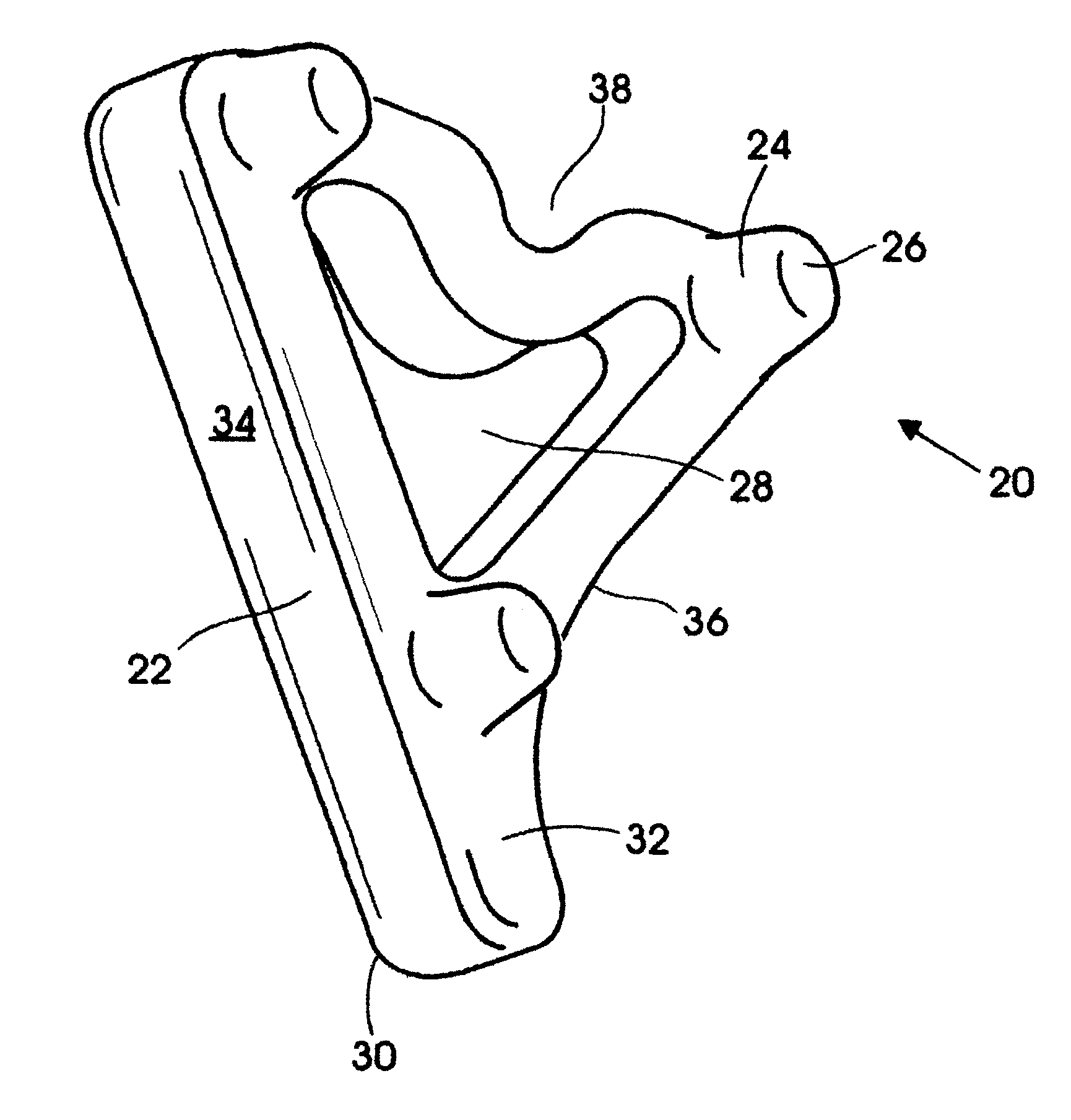
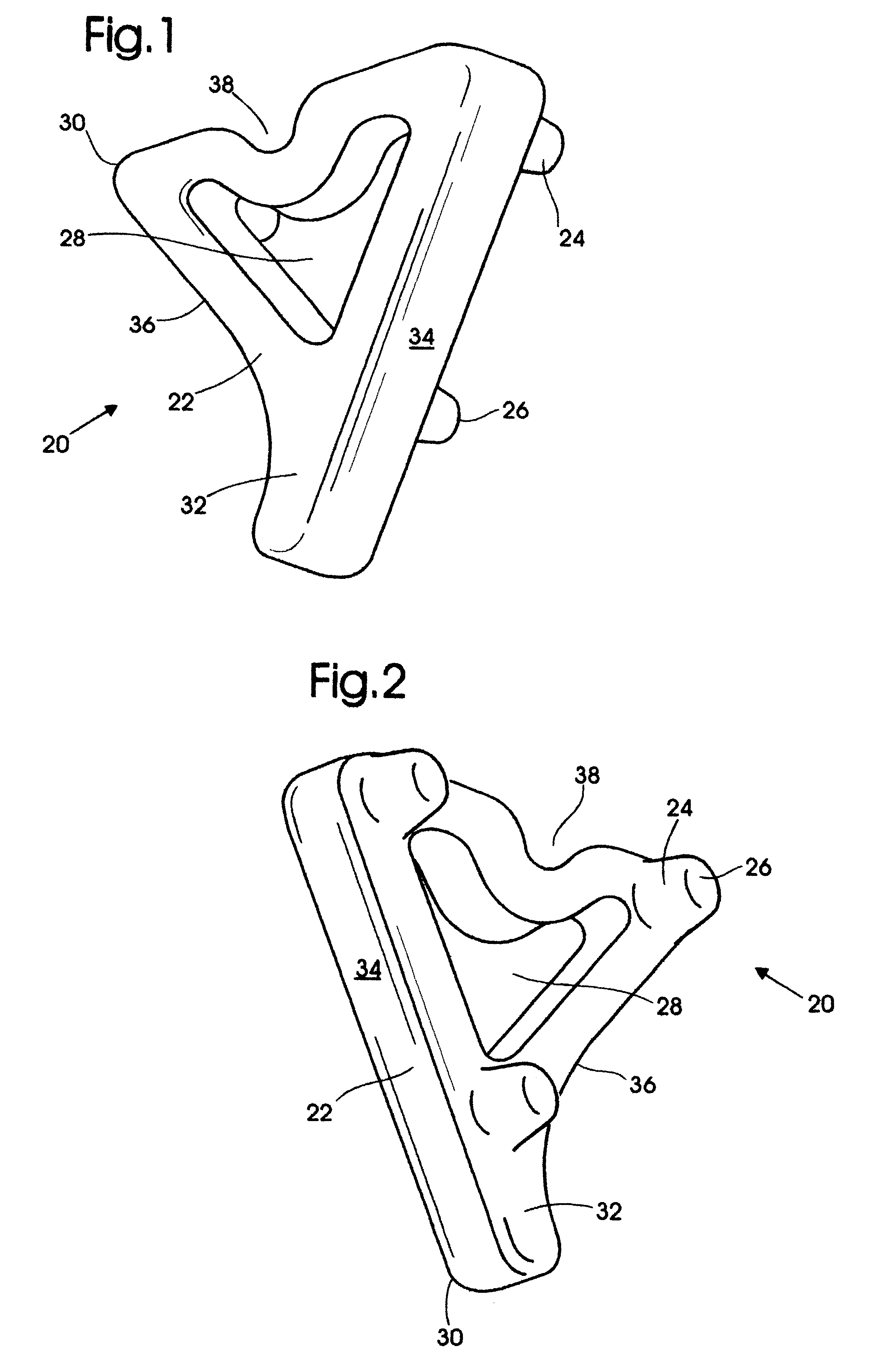
Turning now to the drawings and more particularly to FIG. 1 we have a perspective view of a triangular massage tool 20 as viewed from the top and right. FIG. 2 is a perspective view of the triangular massage tool 20 shown in FIG. 1 as viewed from the bottom and right. The triangular massage tool 20 comprises a generally triangular frame 22 adapted to be held in the palm of one hand; and three leg members 24. The triangular frame 22 has a uniform height thereacross; most preferably this height is generally 17 / 16 inches. Each leg member 24 extends generally from a bottom side corner portion of the frame 22; each leg generally exceeds the thickness of a finger in height; and each leg has a generally rounded bottom portion 26.

Most preferably the legs 24 are generally circular in cross section and the rounded bottom portion 26 is generally semi-spherical. A generally semi-spherical bottom leg portion 26 was found to be far more satisfactory for massaging, than a leg 24 having a flat bott...


PUM


Abstract

An aesthetic and highly functional massage tool is disclosed which comprises a generally triangular frame adapted to be held in the palm of one hand. It has three leg members, each leg member extending generally from a bottom side corner portion of the frame a height generally exceeding the thickness of a finger. Each leg having a generally rounded bottom portion. The legs and triangular frame are monolithically molded from plastic. The frame has a generally triangular opening so that one may extend their fingers therethrough and around a side portion of the frame. This triangular design enables one to securely and comfortably hold the massage tool in multiple positions while during use. This is important because use in any one position tires particular muscles of the massageur. It also facilitates massaging different body portions in differing manners. The triangular void facilitates wrapping one's fingers around the massage tool. It enables one to slide the tool along while pushing downwardly on it. One's hand effortlessly falls within the triangular void and over the exterior of the triangular frame sufficiently to prevent the tool from slipping out from beneath one's hand. The triangular void also allows one to massage holding the tool in an upright position. In the most preferred embodiment the generally triangular frame has the shape of a heart and the plastic is marbled in more than one color.

Description

This invention relates to hand massage tools which are motivated wholly by the massager. More particularly this invention relates to such tools which are ergonomically designed so that they may be easily held and used to massage with minimal muscle fatigue.U.S. Pat. No. Design 346, 4491 is for a rectangular massager having a planar hand held portion with four corner massaging legs, each leg having a flat bottom side portion. The problem with this massager is that it is tiresome to hold on to. Additionally it tends to distribute pressure disproportionately on the massaging legs; those legs under the heel of the hand receive the majority of the pressure. Another problem with this massager is that the massaging legs have flat bottom side portions. The problem with this is that the corner or arris of the bottom side portion of the leg tends to bite into the body when the massager is pushed therealong.OBJECTS AND STATEMENT OF THE INVENTIONIt is an object of this invention to disclose a m...

Claims


Application Information

Patent Timeline
Patent Type & Authority Patents(United States)
IPC IPC(8): A61H7/00
CPCA61H7/001
Inventor GOULDING-THOMPSON, BONNIE L.THOMPSON, MICHAEL
Owner GOULDING THOMPSON BONNIE L
Learn More