Eureka AIR delivers breakthrough ideas for toughest innovation challenges, trusted by R&D personnel around the world.

System and method for monitoring pressure, flow and constriction parameters of plumbing and blood vessels

a technology of pressure monitoring and flow, applied in the field of system and method for monitoring pressure, can solve problems such as invasive methods, diagnostic and plumbing installations, and their invasiveness

Inactive Publication Date: 2001-05-29
TELESENSE
View PDF19 Cites 305 Cited by
  • Summary
  • Abstract
  • Description
  • Claims
  • Application Information

AI Technical Summary

Benefits of technology

The present invention successfully addresses the shortcomings of the presently known configurations by providing a miniaturized, sensitive and non-invasively activatable system useful in monitoring pressure, flow and constriction parameters in a pipe such as a blood vessel.

Problems solved by technology

The invasive methods suffer two major drawbacks for application in human diagnostics and plumbing installations.
The first is their invasiveness.
As a result, without positional information, or alternatively prolonged probing, the measurement is inaccurate.
The methods described hereinabove, in which external contrast agents are traced, suffer a major drawback when employed for medical purposes, since in the course of their application, an external contrast agent, some times poisonous or with yet undetermined accumulative effects is administrated to the human body.

Method used


Image

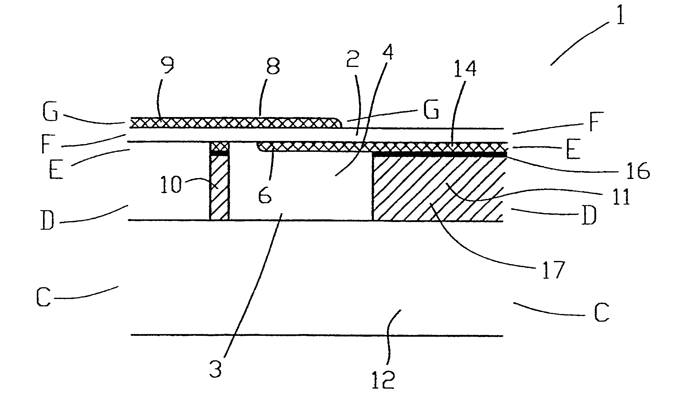
  • System and method for monitoring pressure, flow and constriction parameters of plumbing and blood vessels
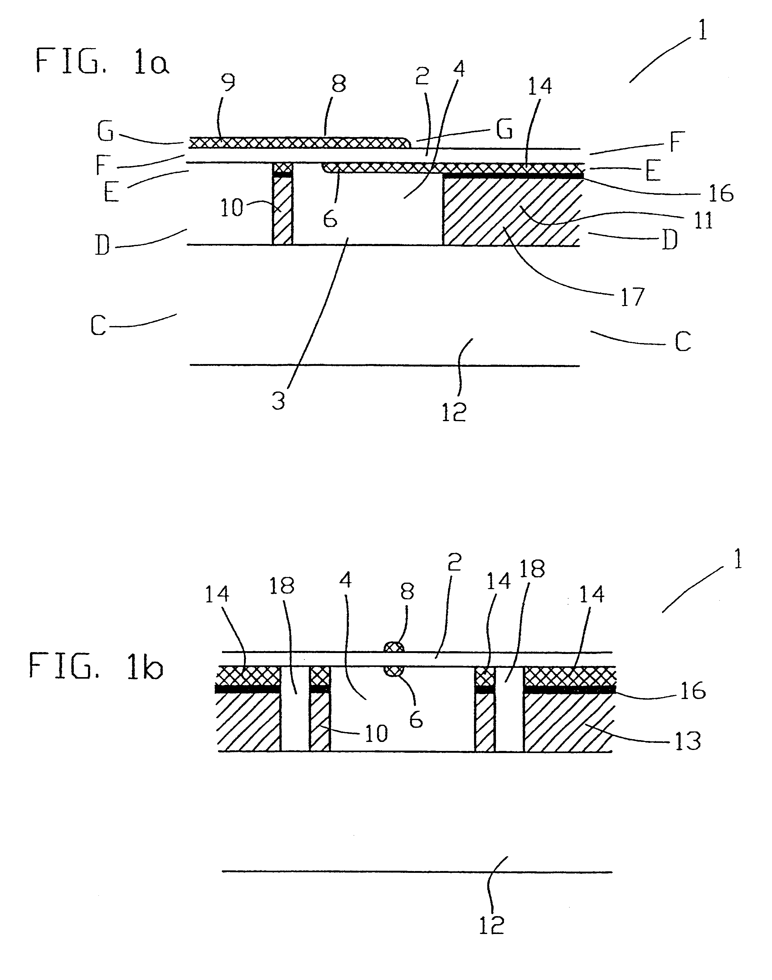
  • System and method for monitoring pressure, flow and constriction parameters of plumbing and blood vessels
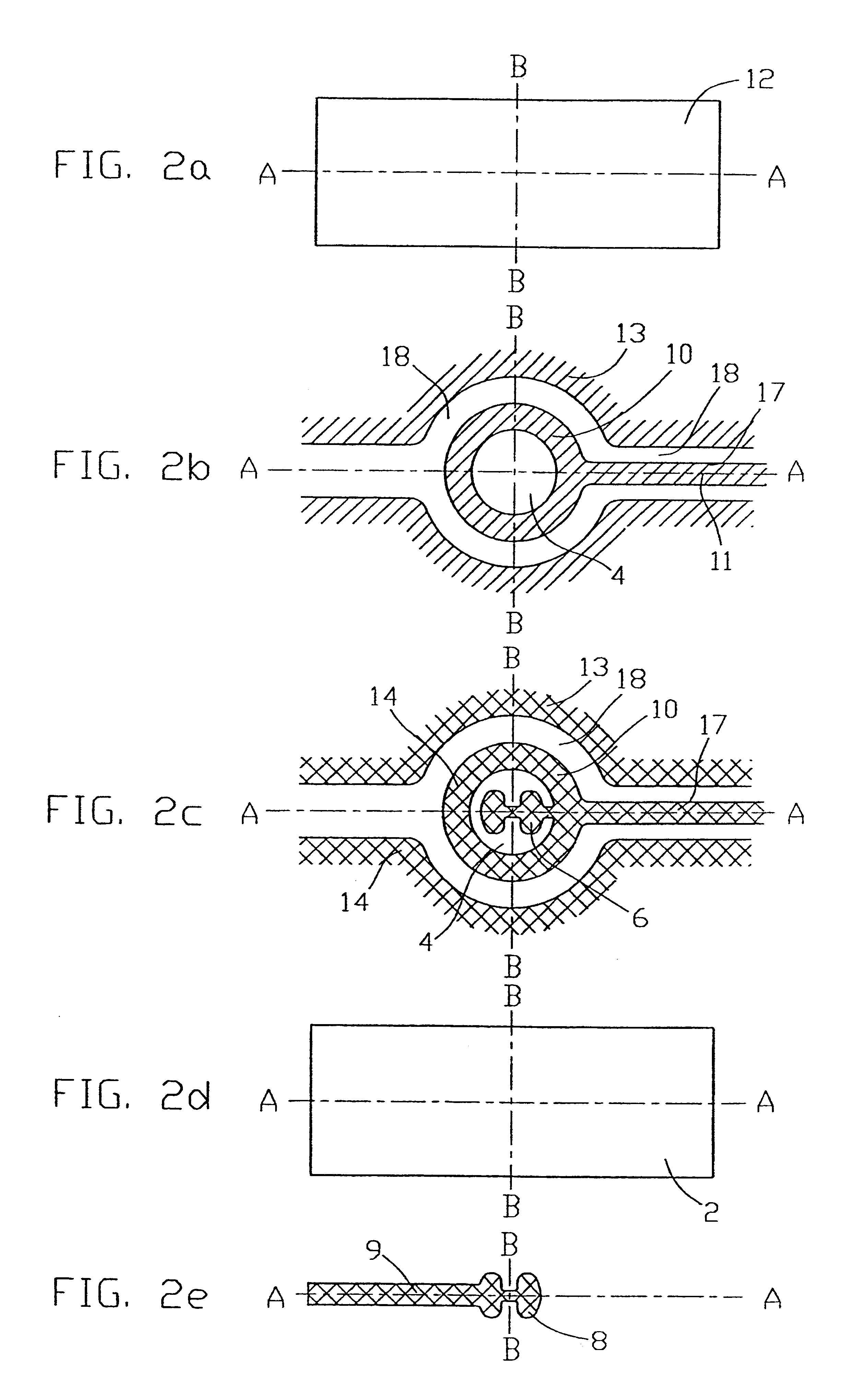
  • System and method for monitoring pressure, flow and constriction parameters of plumbing and blood vessels

Examples


example 1

Effects of Constrictions on the Properties of Pulsatile Flow of Liquids in Elastic Vessels--Theoretical Considerations

Blood flow in the arteries is pulsatile. Blood is ejected from the left ventricle of the heart into the aorta, and the entire vascular system, in sharp pulses. The pulsatile nature of the flow manifests as sharp, periodic fluctuations in the instantaneous blood pressure, as well as in the flow velocity along the arteries.

When a blood vessel is obstructed, the flow rate through the vessel decreases. When this occurs in a coronary artery, ischemia of the heart muscle can result.

The purpose of the following series of experiments is to determine whether and to what degree the degree of constriction of a blood vessel can be determined from instantaneous pressure measurements at various points along its length.

In these experiments a coronary artery was modeled by a flexible latex tube, and the properties of a pulsatile flow of water through constrictions formed in the tube...

example 2

Experimental Protocol

The experimental system used herein is described in FIG. 11. It is based on a computer-controlled electrical valve, which connects via a pipe a high water reservoir to a lower-pressure system. As depicted in FIG. 11, it thus includes two water tanks 200 and 202, connected therebetween via a pipe 204. A computer-controlled electrical valve 206 is implemented on pipe 204, as well as two proximate pressure sensors 208a and 208b. Locations of proximal, midpoint and distal constrictions are indicated by 210a, 210b and 210c.

The electric valve is an on-off, normally closed solenoid-operated valve. It requires a 12V 1A DC power source, which is supplied by a commercial power supply. It is controlled by a custom-build control box, which contains a relay operated from a TTL 5V external control signal, as well as various switches and indicators. The valve opens quite rapidly, taking no more than 10-15 msec to open completely. Closure is slower, and the valve takes roughly ...

example 3

Experimental Procedure The experiment itself is divided into 3 runs as follows:

Run A--Proximal constrictions.

In this run constrictions are placed proximal (upstream) to the sensor assembly.

Run B--Midway constrictions.

In this run constrictions are placed in the middle between the pairs of sensors.

Run C--Distal constrictions.

In this run constrictions are placed distal (downstream) from the sensor assembly.

The experimental procedure for each of the runs is as follows:

Perform a measurement for an open constriction. This is the baseline for comparison.

Perform a measurement for constriction diameters 3, 2.5, 2, 1.5, 1, 0.5 mm. Save the two narrowest openings for last, as they are the most difficult to perform.

A measurement consists of the following steps:

Fit the desired constriction at the proper place.

Open the taps to let water flow through the constriction. Make sure that all the air bubbles come out. This is rather difficult to do for the 0.5 mm constriction, and possibly for the 1 mm ...


PUM


Abstract

The present invention provides a system and method of quantifying flow, detecting a location of an obstruction and quantifying a degree of the obstruction in a pipe characterized in pulsatile flow. The method includes the steps of (a) attaching at least two spaced pressure sensors onto inner walls of the pipe; (b) using the at least two spaced pressure sensors for recording pressure records associated with each of the at least two pressure sensors within the pipe; and (c) using the pressure records for quantifying the pulsatile flow in the pipe, for detecting the location of the obstruction in the pipe and for quantifying the degree of the obstruction in the pipe.

Description

FIELD AND BACKGROUND OF THE INVENTIONThe present invention relates to the field of monitoring pressure, flow and constriction parameters of plumbing and / or blood vessels. More particularly, the present invention relates to a system and method for monitoring pressure, flow rate and constriction degree and location within plumbing and blood vessels using an acoustical approach. Most particularly, the present invention relates to a system having a device transplantable within a plumbing installation or a blood vessel, which device collects data related to the above parameters and transmits that data to a second device of the system, external to the installation or body, so as to enable real-time non-invasive monitoring of such parameters.Availability of real-time quantitative information regarding, for example, coronary flow may be of great value for the cardiac physician. For example, following a stent insertion or graft implantation, such data may be exploited for monitoring new cons...

Claims


Application Information

Patent Timeline
IPC IPC(8): A61B5/00A61B5/053G01F1/34G01F1/72G01F1/36H01L41/113H04R17/00A61B5/0215A61B5/026H01L41/09H03H9/17
CPCA61B5/0031A61B5/02158A61B5/026A61B5/0535A61B5/413G01F1/36G01F1/72H01L41/1132H04R17/00A61B2562/028A61N1/37288A61B5/0295H10N30/302
Inventor PORAT, YARIVTSALIAH, YOSEFDORON, EYAL
Owner TELESENSE
Why Eureka
Eureka Blog
Learn More