
Needle guard and assembly

a technology of needle guards and needles, applied in the direction of guide needles, infusion needles, intravenous devices, etc., can solve the problems of unsatisfactory guards, user's touch of the sides, and the danger of blood-splash from exposed used needles, so as to reduce the danger of needle-stick injury and blood-splash contamination.

Inactive Publication Date: 2001-05-22
NOBLE HOUSE GROUP
View PDF22 Cites 49 Cited by
  • Summary
  • Abstract
  • Description
  • Claims
  • Application Information

AI Technical Summary

Benefits of technology

It is therefore an object of the present invention to provide guards for use with medical needle assemblies, and to provide combined guards and needle assemblies, which will address at least some of the practical disadvantages of the guards and combinations of the prior art while minimising the danger of needle-stick injury and blood-splash contamination.

Problems solved by technology

`Blood-splash` is used herein generically to signify the dripping of any liquid from the point of a used needle and is a particular danger with needle assemblies because their trailing tubes often contain blood.
Guards of this type are not ideal because blood splash can occur through their open front ends and / or side slots.
Not only is there danger of needle stick blood-splash from the exposed used needle during this manoeuvre, but the user is likely to touch the sides of the exposed needle as he / she attempts to insert the wings into their slots in the fingers of the guard.
However, blood-splash can still occur from the open front end of the sleeve and frictional jamming is an insecure manner of securing the needle and its hub in a guard.
In one case (Utterberg U.S. Pat. No. 5,112,311 FIGS. 23-25), the slots are fitted with `curtains` or flaps (identified by numeral 403 by Utterberg) to mitigate this danger but, if the curtains are to be effective in that regard, they will make it difficult to move the wings of the needle assembly along the slots.
In another case (U.S. Pat. No. 5,433,703 to Utterberg), a separate cap is provided for covering the open end of the guard after the needle has been withdrawn therein, but the cap is another item to manipulate and is an additional expense.
Again, however, the addition of such gates is expensive and possibly unreliable since they require additional and separate moving parts.

Method used


Image

  • Needle guard and assembly
  • Needle guard and assembly
  • Needle guard and assembly

Examples


Embodiment Construction

Having broadly portrayed the nature of the present invention, particular examples will now be described by way of illustration only. In the following description, reference will be made to the accompanying drawings in which:

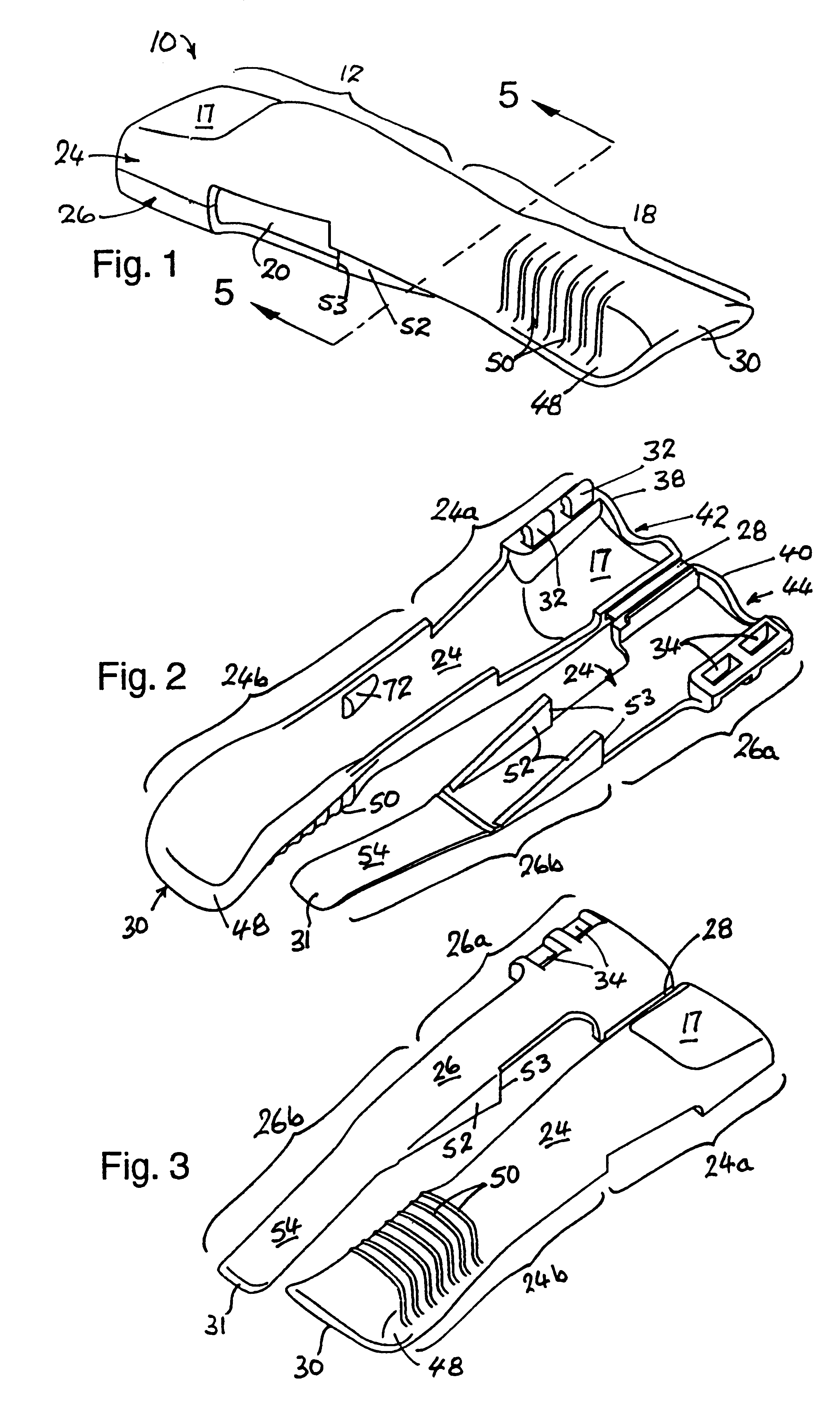
FIG. 1 is a perspective view of the assembled needle guard that forms the first example;

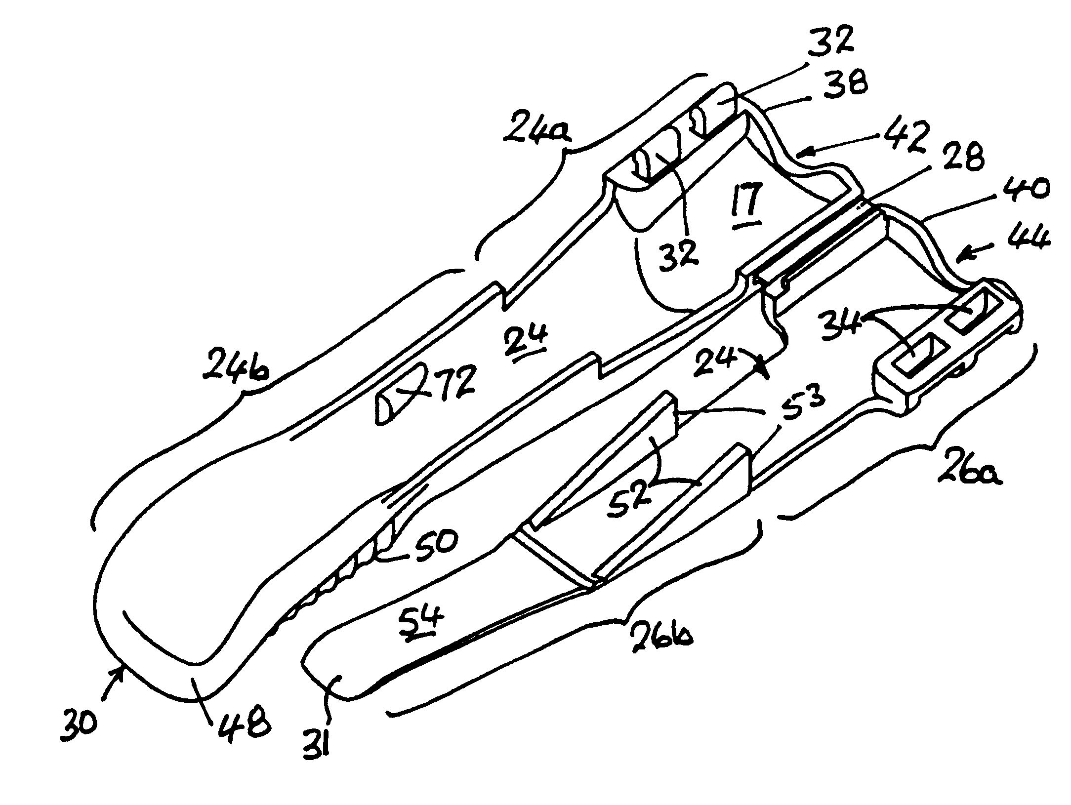
FIG. 2 is a perspective view of the interior of the guard of FIG. 1 in the unfolded or un-assembled state;

FIG. 3 is a perspective view of the exterior of the guard of FIG. 1 in the unfolded or un-assembled state;

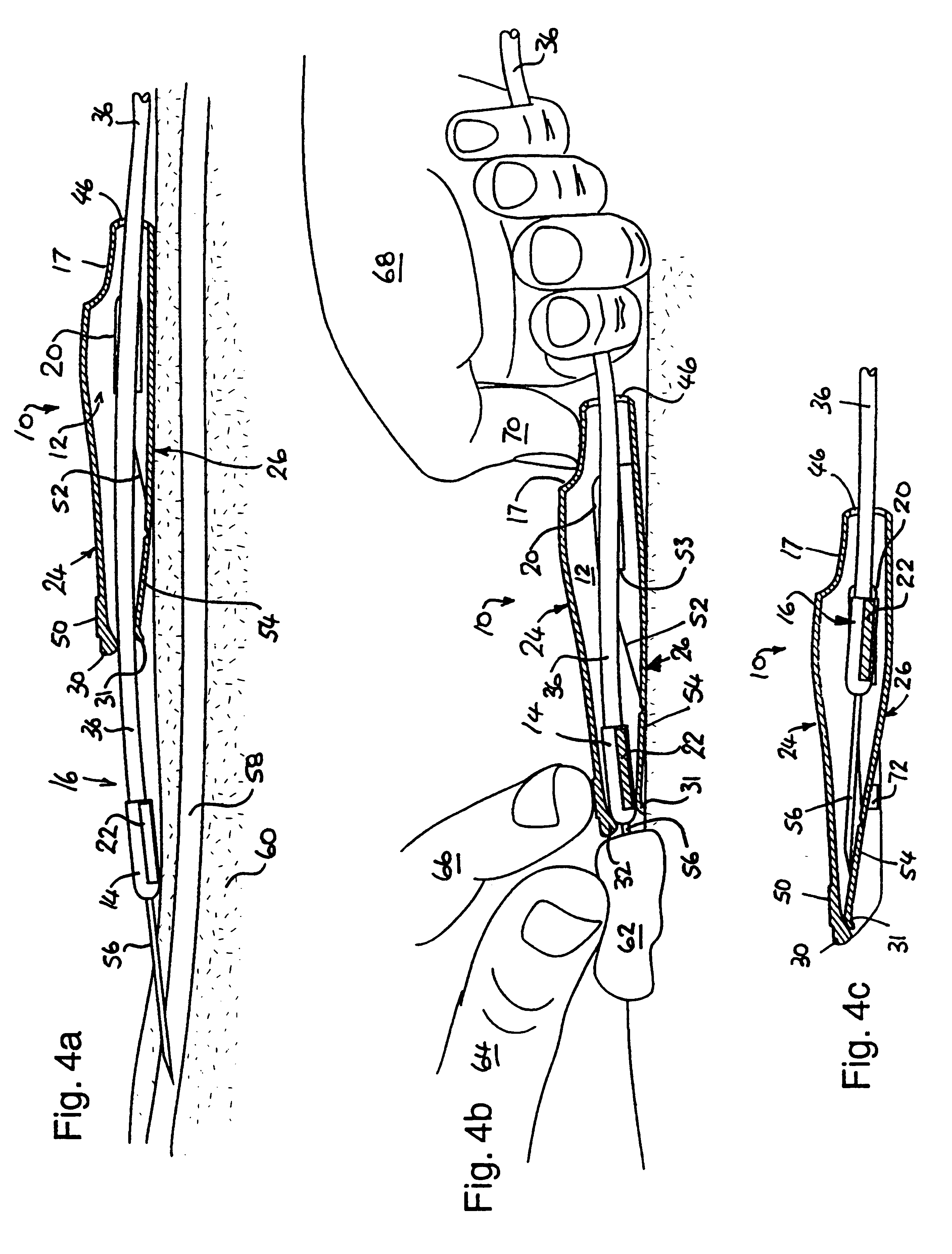
FIGS. 4a, 4b and 4c are sectional diagrammatic elevations of the guard of the first example showing a winged needle assembly just after insertion of the needle (FIG. 4a), as it is being withdrawn into the guard (FIG. 4b) and after it has been fully withdrawn into the guard (FIG. 4c);

FIG. 5 is a cross-section of the guard of FIG. 1 taken on section plane 5--5 indicated in FIG. 1;

FIG. 6a is a longitudinal sectional elevation of the guard which forms the second example of...


PUM


Abstract

Needle guards are disclosed for use with needle assemblies comprising a needle hub that joins a flexible trailing tube to a medical needle, the normally open front ends of the guards being closeable after a needle and hub have been pulled therein by the trailing tube. In one example (FIG. 4c), a guard (10) has a stiff upper sidewall (24a) of an inverted U-shape and a flexible lower sidewall (26b) that fits inside the upper sidewall and is resiliently biased to bring its front end (31) into contact with the front end (30) of upper sidewall (24b) so as to close the front aperture of the guard after the needle assembly (16) has been withdrawn into the guard. The lower sidewall (26b) can be locked or clipped into the upper sidewall (24b) by pressing lower sidewall passed catches (72). In this way, the needle is completely and safely enclosed after use to reduce the danger of needle-stick injury and blood-splash contamination.

Description

This invention relates to guards for use with needle assemblies and to combined guard and needle assemblies.The needle assemblies concerned are those which have a tubular medical needle pointed at the front end and joined by a hub at the rear or butt end to a flexible trailing tube so that fluids can be conveyed to or from a patient via the tube and needle. The hub is commonly formed from plastic, injection-moulded onto the needle and used to hold the needle during insertion. One or two flexible lateral wing-like extensions may be moulded integrally with the hub to assist in manipulating the needle and in strapping the assembly to the patient, after the needle has been inserted into a vein. Such needles are called `butterfly` or `winged` needles and are typically used for intravenous infusion or phlebotomy. Needle assemblies without wings formed on their hubs are called `wingless` and are commonly used in blood collection. The guards of the present invention are applicable to both w...

Claims


Application Information

Patent Timeline
IPC IPC(8): A61M25/06A61M5/32A61M5/158
CPCA61M25/0631A61M5/3271A61M2005/3246A61M2005/325
Inventor DILLON, JAGMOHANBIR SINGHMOBBS, WILLIAM LEONARD
Owner NOBLE HOUSE GROUP
Learn More