Battery pack
- Summary
- Abstract
- Description
- Claims
- Application Information
AI Technical Summary
Problems solved by technology
Method used
Image
Examples
ninth embodiment
In the following, a battery pack according to the present invention will be described with reference to FIGS. 44 to 46.
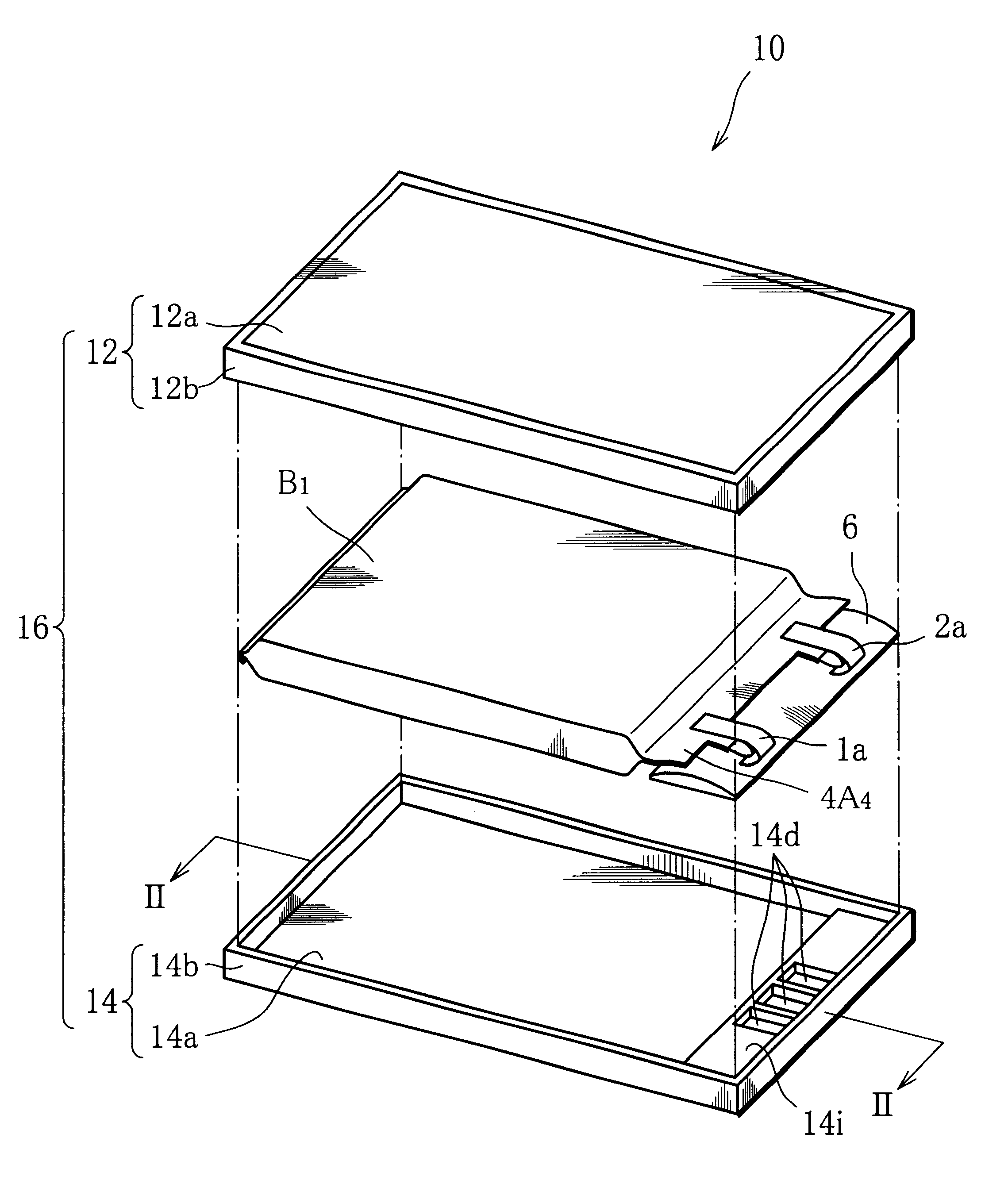
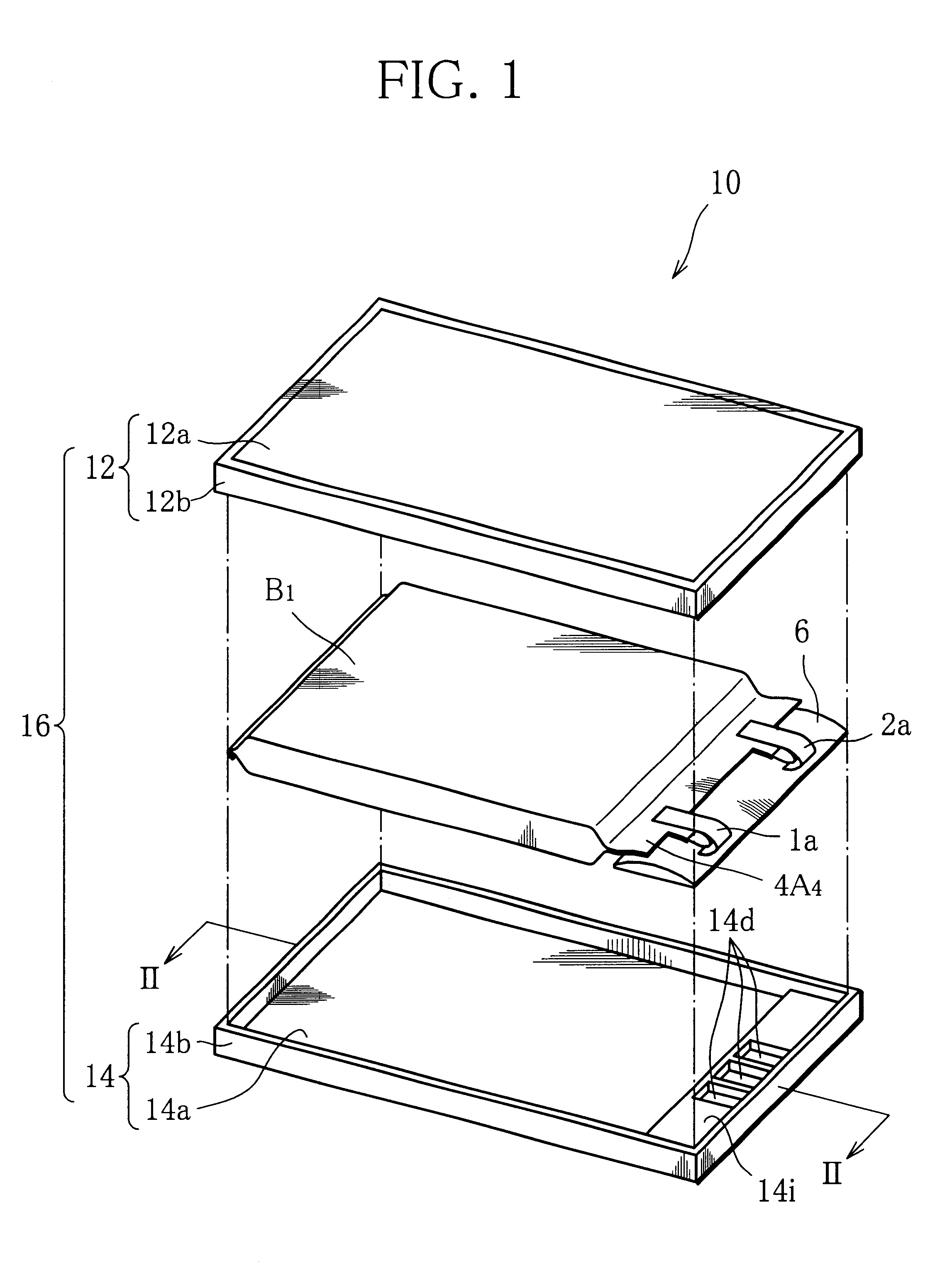
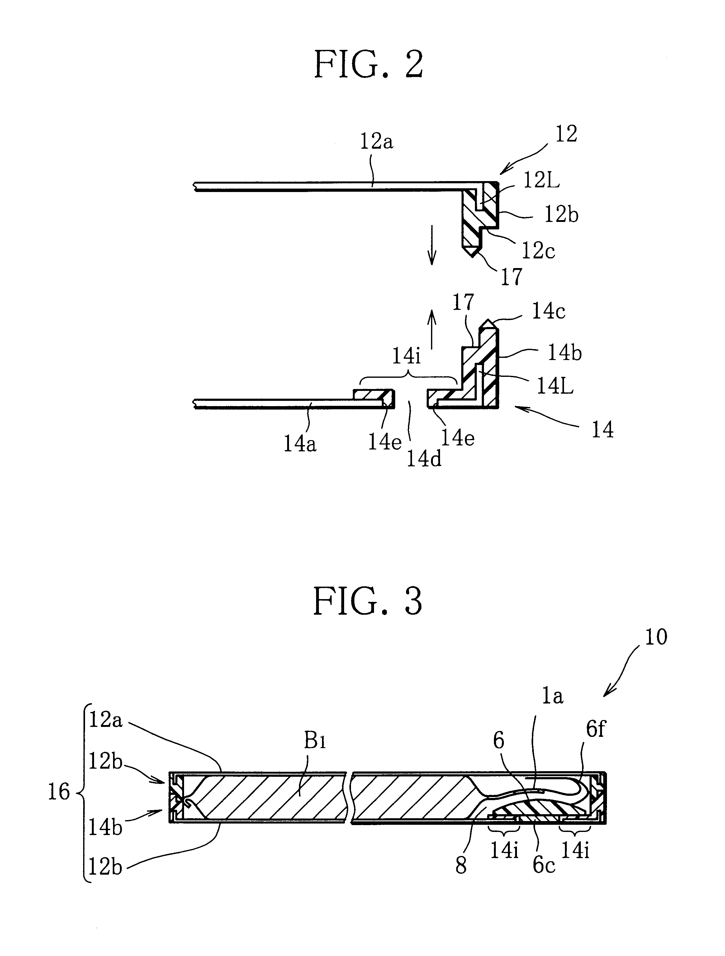
The battery pack of this embodiment is characterized in that a resistive element is interposed between a positive tab or a negative tab of a flat battery cell and a circuit board. The resistive element is accommodated in a space 8 in the shape of terrace of the flat battery cell.
As illustrated in FIG. 45, this resistive element 90 comprises two metal foils 90a, 90b made, for example, of Ni, and a conductive polymer sheet 90c having a positive temperature coefficient, interposed between the two metal foils 90a, 90b . Generally, the polymer sheet 90c has a thickness in a range of 0.5 to 1.5 mm. In addition, the conductive polymer sheet 90c is formed of a polymer, which is an insulating material, dispersed with an electrically conductive material, for example, carbon grains, such that the conductive polymer sheet 90c exhibits a lower resistance in a normal state or at ...
tenth embodiment
In the following, a battery pack according to the present invention will be described with reference to FIGS. 47 to 49.
As illustrated in FIG. 47, the battery pack 202 of this embodiment is mounted to an electronic device 202 for practical use. The battery pack 201 is formed with a terminal set A11, while the electronic device 202 is formed with a terminal set B11 which can be connected to the terminals A11. The terminal sets A11, B11 are mechanically engaged and integrated as the battery pack 201 is mounted to the electronic device 202.
Therefore, even if an external force is applied entirely to the battery pack 201 and the electronic device 202 to cause deformation such as deflection, the integrated terminal sets A11, B11 through firm engagement, are free from failed contact which would otherwise be experienced by flat plate terminals.
As illustrated in FIG. 48, the battery pack 201 comprises a flat battery cell 201A such as a film cell; a circuit board 201B connected to positive and...
eleventh embodiment
FIG. 50 illustrates a battery pack according to the present invention which has a terminal set A12 having a structure different from that of the terminal sets A11 illustrated in FIG. 48.
The terminal set A12 comprises a resin molding 203 generally in the shape of box which is open on one side; and terminals 203b fixed on the bottom wall of the molding 203 by molding. The terminal set A12 is mounted at a predetermined position on the top surface of a circuit board 201B.
PUM
 Abstract
Description
Claims
Application Information
 - R&D
- Intellectual Property
- Life Sciences
- Materials
- Tech Scout
- Unparalleled Data Quality
- Higher Quality Content
- 60% Fewer Hallucinations
Browse by: Latest US Patents, China's latest patents, Technical Efficacy Thesaurus, Application Domain, Technology Topic, Popular Technical Reports.
© 2025 PatSnap. All rights reserved.Legal|Privacy policy|Modern Slavery Act Transparency Statement|Sitemap|About US| Contact US: help@patsnap.com


