Optical transmitting apparatus and optical receiving apparatus, and optical communicating method

a technology of optical communication and optical receiving, applied in the field of optical communication methods, can solve the problems of low network extensibility, limited number of subscribers to the number of wavelengths, and inability to increase the number of subscribers of the optical communication system, so as to improve the accuracy of communication, increase the extensibility of the network, and efficiently use the transmission band

Inactive Publication Date: 2001-04-10
FUJITSU LTD
View PDF11 Cites 15 Cited by
  • Summary
  • Abstract
  • Description
  • Claims
  • Application Information

AI Technical Summary

Benefits of technology

According to this invention, as described above, it is possible to generate optical signals for the respective plural opposite apparatus using a combination of p optical wavelengths set in advance for each of the plural opposite apparatus (optical receiving apparatus, receiving side apparatus) by the optical signal generating unit of the optical transmitting apparatus (transmitting side apparatus), and transmit wavelength division multiplexed optical signals from the wavelength division multiplexing transmitting unit over the optical communication network. It is therefore possible to configure an optical communicating system which can accommodate subscriber terminals m larger in number than wavelengths n which can be wavelength division multiplexed so as to efficiently use a transmission band of the optical communication system and increase extensibility of the network while keeping an existing performance of wavelength division multiplexing of the network.
Further, it is possible to set a combination of p wavelengths in advance for each of the plural opposite apparatus (optical receiving apparatus, receiving side apparatus) and transmit the signals. It is thereby possible to improve accuracy of communication while preventing transmit signals addressed to a certain opposite apparatus (optical receiving apparatus, receiving side apparatus) from being transmitted to another opposite apparatus (optical receiving apparatus, receiving side apparatus) so as to realize privacy protection, that is, improve communication security.
Further, it is possible to convert data including plural destinations transmit information without privacy that should be transmitted to a plurality of destinations along with private information that should be prevented from being received by an opposite apparatus other than the opposite apparatus (optical receiving apparatus, receiving side apparatus) which are destinations as optical signals. It is thereby possible to do wavelength division multiplexing transmission while selecting wavelengths according to characteristics of a data system that should be transmitted. In particular, it is possible to improve utility of the optical communication system so as to remarkably increase efficiency of a used band in a transmission route.

Problems solved by technology

However, the optical communicating system 100 using the above wavelength division multiplexing technique as shown in FIG. 26 has a disadvantage such that the number of subscribers is limited to the number of wavelengths which can be multiplexed.
However, the above optical communication network shown in FIG. 27 has a low extensibility of the network to increase the number of subscribers of the optical communicating system.

Method used


Image

  • Optical transmitting apparatus and optical receiving apparatus, and optical communicating method
  • Optical transmitting apparatus and optical receiving apparatus, and optical communicating method
  • Optical transmitting apparatus and optical receiving apparatus, and optical communicating method

Examples


first embodiment

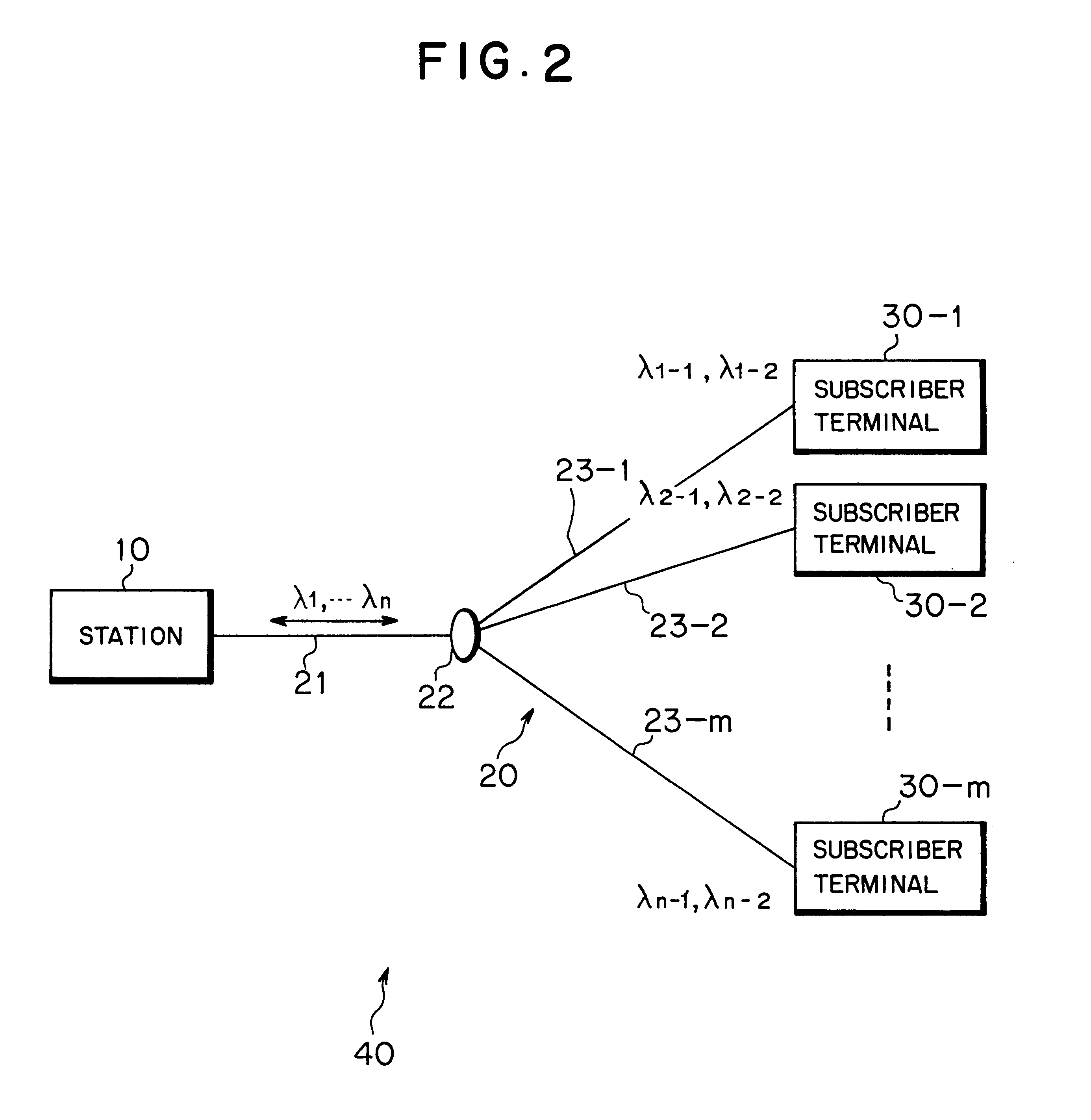
FIG. 2 is a block diagram showing an optical communicating system to which this invention is applied. In the optical communicating system 40 shown in FIG. 2, reference numeral 10 denotes a station (optical transmitting apparatus, transmitting side apparatus). The station 10 can convert transmit data, which is time division multiplexed (TDM) or in the synchronous transfer mode (STM), into wavelength division multiplexed optical signals and transmit the optical signals to the subscriber terminals (optical receiving apparatus, receiving side apparatus) 30-1 through 30-m (m; an integer not less than 2), which are a plurality of opposite apparatus as destinations over an optical communication network 20.

In the optical communication network 20, an optical fiber 21 on the side of the station 10 is connected to each of optical fibers 23-1 through 23-m on the side of the subscriber terminals via an optical coupler 22. Whereby, the station 10 can transmit an optical signal of, for example, n ...

second embodiment

(c) Description of a Second Embodiment

FIG. 17 is a block diagram showing an essential part of a station 10A according to a second embodiment of this invention. The station 10A shown in FIG. 17 is applied similarly to the station 10 in the optical communication system 40 according to the above first embodiment.

The station 10A according to the second embodiment has, differently from that (refer to reference numeral 10) according to the first embodiment, a scramble processing unit 50, instead of the cell duplicating unit 11 and the DMUXs 13-1 and 13-2, and a controlling unit 12A for controlling a process in the scramble processing unit 50. Other structure is basically the same as the first embodiment described above.

The controlling unit 12A has a table for holding destination information correspondingly to header information given by the header attaching unit 17 to control the scramble processing unit 50, the multiplexing units 14-1 through 14-n and the FIFO memory 15 so that transmit ...

third embodiment

(d) Description of a Third Embodiment

FIG. 20 is a block diagram showing a station 10B according to a third embodiment of this invention. The station 10B shown in FIG. 20 is also applied to the optical communicating system 40, similarly to the above first and second embodiments.

As compared with the above first and second embodiments (refer to reference numerals 10 and 10A), the station 10B according to the third embodiment can transmit data which does not require privacy protection as wavelength division multiplexed optical signals along with data (private data) requiring privacy protection. Other structure of the station 10B is basically the same as those according to the first and second embodiments.

The station 10B shown in FIG. 20 has a transmitting system for private data (refer to reference numerals 11, 13-1, 13-2, 14-1 through 14-n and 15) similarly to the first embodiment, besides a header attaching unit 17A, a data replicating unit 11A and an FIFO memory 15A as a data transmi...


PUM


Abstract

An optical transmitting apparatus used in an optical communicating system in an optical communication network using a broad-band characteristic of fibers, which can transmit wavelength division multiplexed optical signals over the optical communication network, has an optical signal generating unit for generating optical signals for the respective plural opposite apparatus by using a combination of p (p; an integer not less than 2) wavelengths set in advance for each of the plural opposite apparatus, and a wavelength division multiplexing transmitting unit for wavelength division multiplexing the optical signals generated by the optical signal generating unit and transmitting the optical signals, thereby accommodating subscriber terminals larger in number than the number of times of wavelength division multiplexing while realizing privacy protection.

Description

The present invention relates to an optical transmitting apparatus and an optical receiving apparatus, and an optical communicating method suitable for use in an optical communicating system for an optical communication network utilizing broad band characteristics of fibers.The optical communication network can transmit a large volume of information as compared with a network using general copper cables. In recent years, the optical communication network draws attention as a network which provides a multi-media service such as CATV (Cable Television), VOD (Video on Demand) or the like.FIG. 26 is a block diagram showing an example of an optical communicating system for providing a multi-media service. In an optical communicating system 100 shown in FIG. 26, a single station 101 is connected to an optical coupler 102 on a transmission route through one optical fiber 103, and a plurality (n, here) of subscriber terminals 104-1 through 104-n are connected to the optical coupler 102 thro...

Claims


Application Information

Patent Timeline
Patent Type & Authority Patents(United States)
IPC IPC(8): H04J14/02H04J14/08H04B10/03H04B10/032H04B10/07H04B10/272H04J14/00
CPCH04J14/0226H04J14/0282H04J14/08H04J14/0246H04J14/025
Inventor TOCHIO, YUJI
Owner FUJITSU LTD
Why Eureka
Try Eureka