
Staged combustion of a low heating value fuel gas for driving a gas turbine

a fuel gas and low heating value technology, applied in the direction of combustion types, combustion of lump and pulverized fuel, lighting and heating apparatus, etc., can solve the problems of fuel gas, insufficient space for fuel gas, and inconvenient design

Inactive Publication Date: 2001-03-13
MARATHON OIL CO +1
View PDF37 Cites 271 Cited by
  • Summary
  • Abstract
  • Description
  • Claims
  • Application Information

AI Technical Summary

Problems solved by technology

As such, a conventional central burner nozzle, which is designed for high heating value fuel gases, is not sufficiently large to accommodate the large volume of low heating value fuel gas required to achieve the necessary heat release for the burner assembly.
Conversely, the annular flow region is overly large, permitting an excessive air to fuel ratio in the burner assembly which is outside the flammability envelope of the air / fuel mixture.
However, this design is only operable within a narrow range of conditions and cannot be utilized with turbines having internal combustors.

Method used


Image

  • Staged combustion of a low heating value fuel gas for driving a gas turbine
  • Staged combustion of a low heating value fuel gas for driving a gas turbine
  • Staged combustion of a low heating value fuel gas for driving a gas turbine

Examples


Embodiment Construction

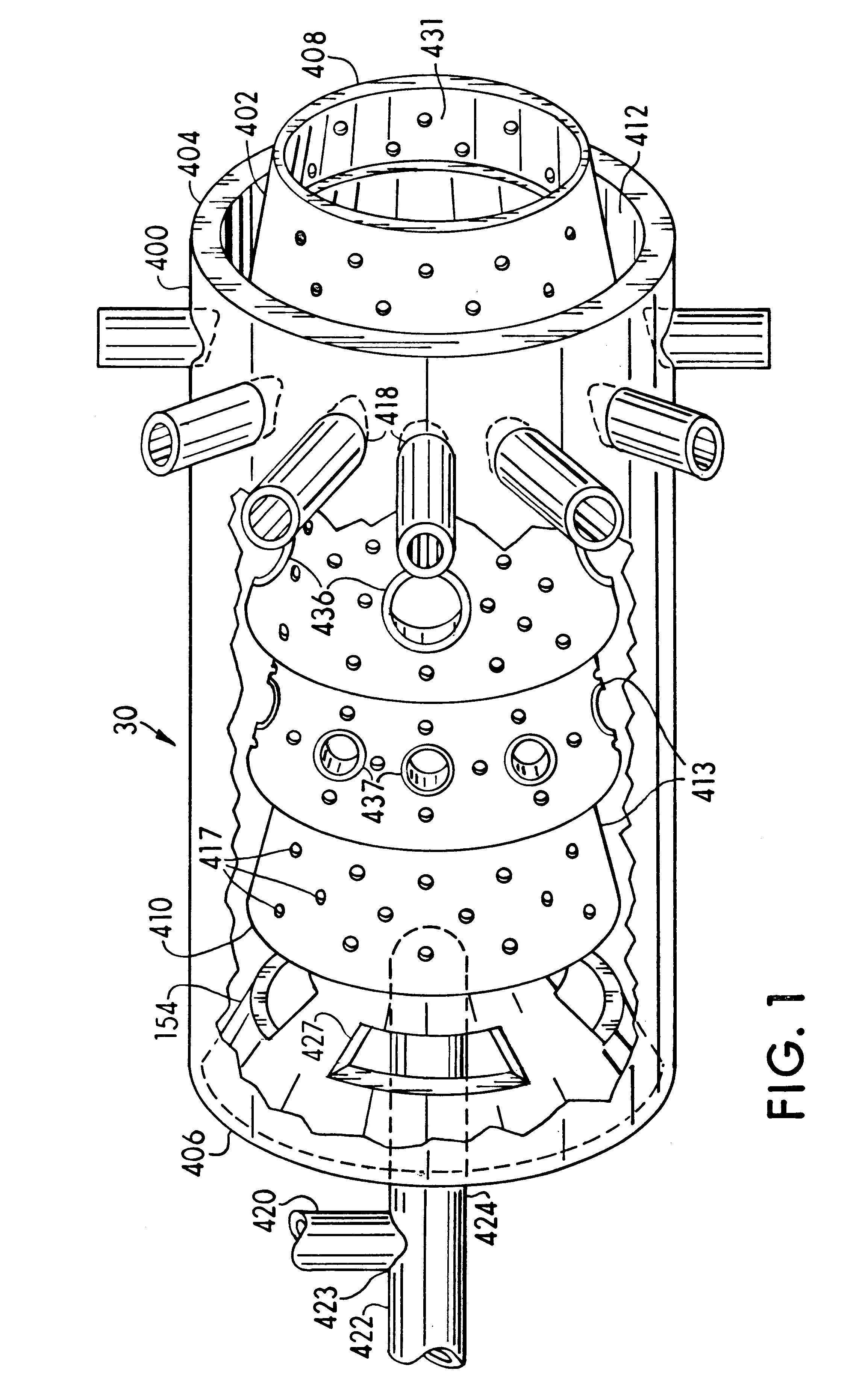
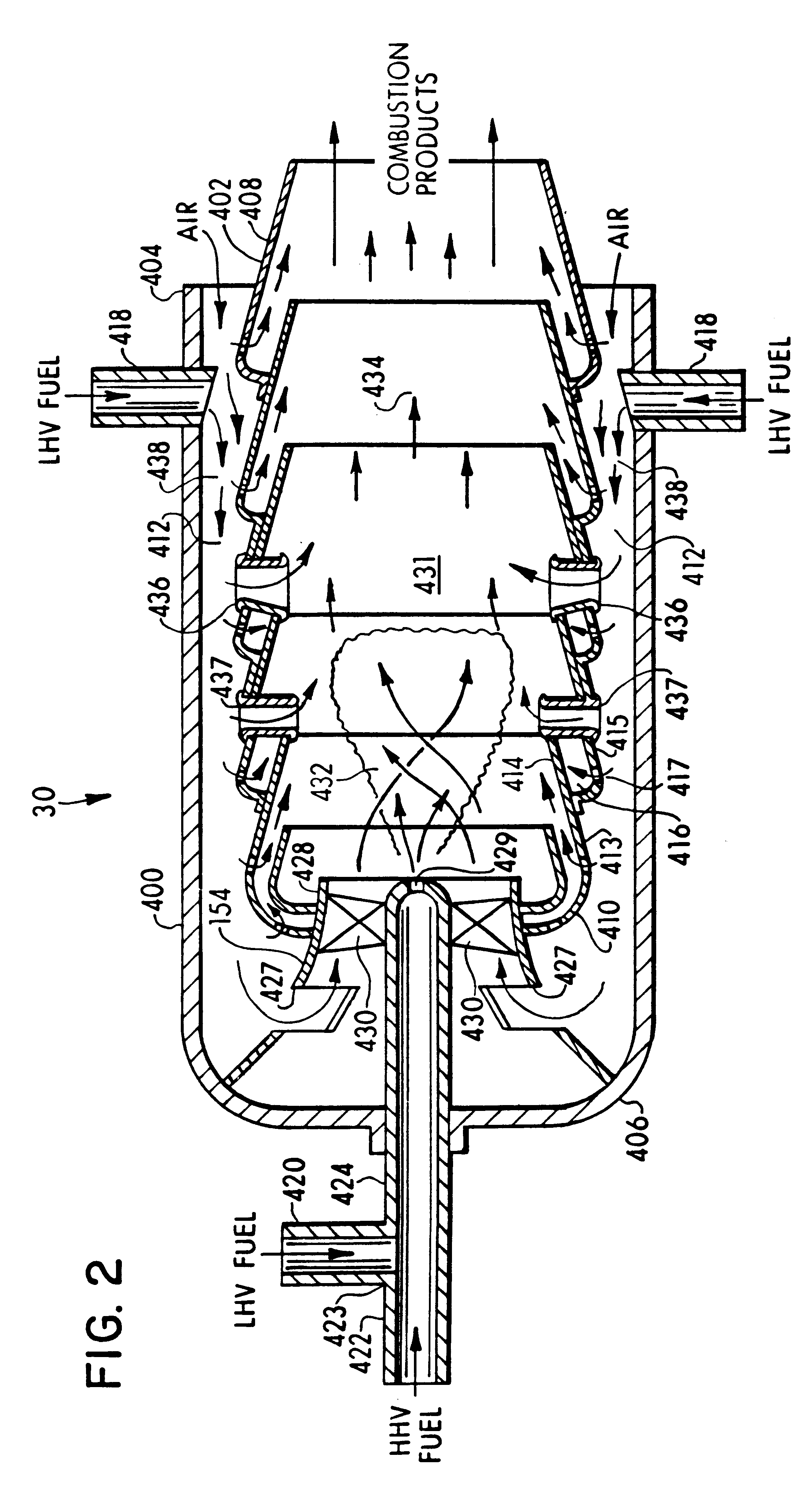
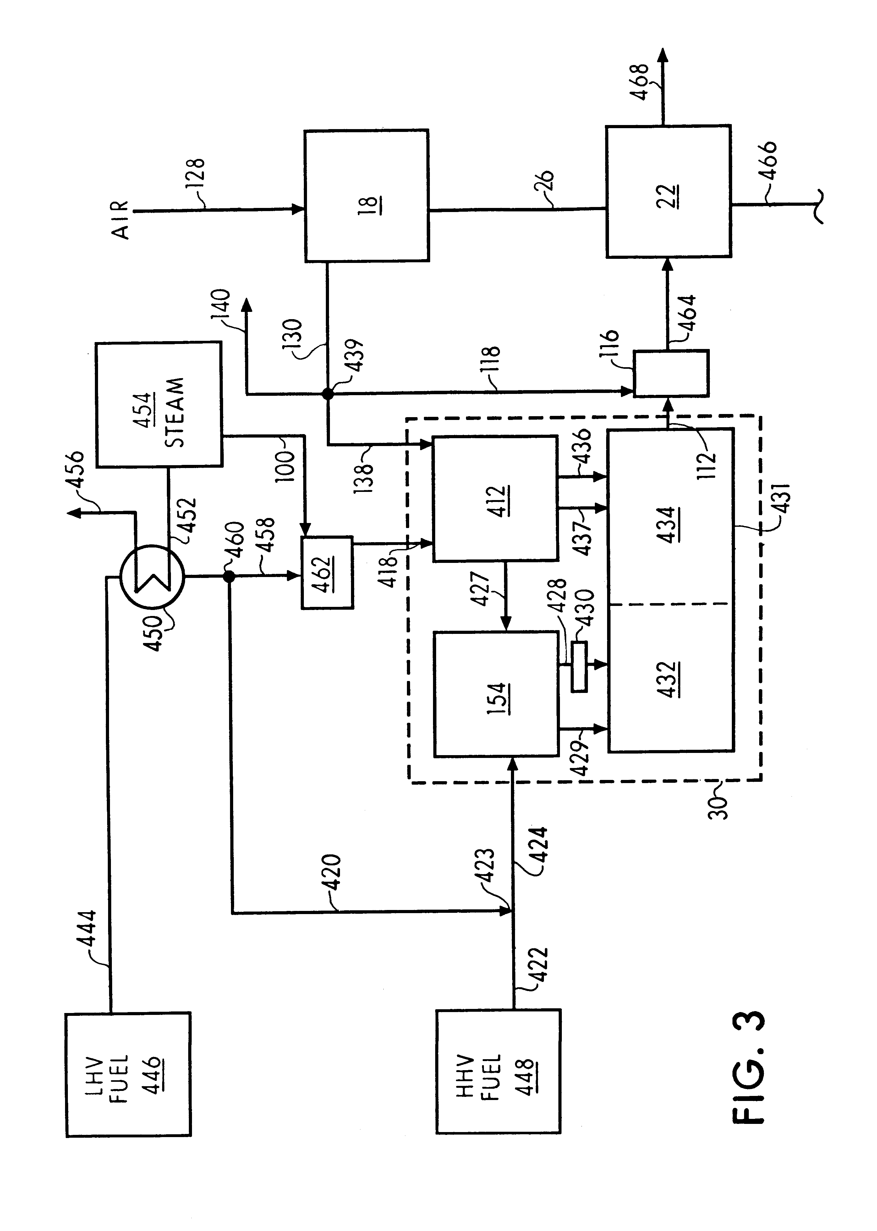
The present invention relates to a process for combusting a low heating value (LHV) fuel gas in a combustor and driving an associated gas turbine with the resulting hot gaseous combustion products. Referring initially to FIG. 1, a combustor, generally designated 30, is shown which has utility in the combustion process of the present invention. The combustor 30 is termed an "external combustor" because it is not structurally integral with the associated gas turbine (not shown in FIG. 1). It is noted, however, that practice of the present process is not limited to external combustors. As will be apparent to the skilled artisan, the present process may likewise be practiced with internal combustors which are structurally integral with the associated gas turbine.

The combustor 30 described herein for purposes of illustration includes a casing 400, termed the "combustor can", and a combustion liner 402. The combustor can 400 is cylindrically configured with a substantially open upstream e...


PUM

PropertyMeasurementUnit
Poweraaaaaaaaaa
Ratioaaaaaaaaaa
Velocityaaaaaaaaaa

Abstract

A process is provided for combusting a low heating value fuel gas in a combustor to drive an associated gas turbine. A low heating value fuel gas feed is divided into a burner portion and a combustion chamber portion. The combustion chamber portion and a combustion air are conveyed into a mixing zone of the combustor to form an air / fuel mixture. The burner portion is conveyed into a flame zone of the combustor through a burner nozzle while a first portion of the air / fuel mixture is conveyed into the flame zone through a burner port adjacent to the burner nozzle. The burner portion and first portion of the air / fuel mixture are contacted in the flame zone to combust the portions and produce flame zone products. The flame zone products are conveyed into an oxidation zone of the combustor downstream of the flame zone while a second portion of the air / fuel mixture is also conveyed into the oxidation zone. The second portion is combusted in the oxidation zone in the presence of the flame zone products to produce combustion products. The combustion products are conveyed into the associated gas turbine and drive the gas turbine.

Description

1. Technical FieldThe present invention relates generally to a process for combusting a fuel gas to drive a gas turbine and, more particularly, to a process for combusting a low heating value fuel gas in a combustor by dividing the fuel gas into a plurality of portions and combusting each portion of the fuel gas in a different stage of the combustor.2. Background InformationStandard commercial combustors for gas turbines employ burner assemblies and combustion chambers typically designed to combust relatively high heating value fuels, such as natural gas which has a heating value in a range from about 50,000 to 60,000 kJ / kg. The stoichiometric demand for air in a conventional commercial burner assembly combusting a high heating value fuel gas is usually at least 10 volumes of combustion air for each volume of fuel gas fed to the burner assembly. In accordance with the swirl-stabilized combustion mechanism utilized by most commercial burner assemblies, the combustion air is fed to th...

Claims


Application Information

Patent Timeline
IPC IPC(8): C01B3/38C01B3/00C07C1/04C07C1/00F23R3/36F23R3/28F23R3/34F23C6/04F23C6/00
CPCC01B3/382C07C1/0485F23C6/047F23R3/346F23R3/36C01B2203/0244C01B2203/0415C01B2203/062C01B2203/0844C01B2203/0883C01B2203/0894C01B2203/1052C01B2203/1241C01B2203/127C01B2203/1276C01B2203/141C01B2203/142C01B2203/148C01B2203/1604C01B2203/82C01B2203/84F23C2201/301F23R2900/00002
Inventor WAYCUILIS, JOHN J.
Owner MARATHON OIL CO
Learn More