
Laser light

a technology of laser light and light source, which is applied in the direction of lighting and heating equipment, light source combinations, instruments, etc., can solve the problems of limited dexterity, users' ability to see clearly, communication verbally, and inability to provide precise high-visibility illumination

Inactive Publication Date: 2001-03-06
KRIETZMAN MARK HOWARD
View PDF11 Cites 45 Cited by
  • Summary
  • Abstract
  • Description
  • Claims
  • Application Information

AI Technical Summary

Problems solved by technology

Watertight flashlights may solve some problems but do not provide the precise highly visible illumination and communication a submersible laser emitting illuminator yields.
In the underwater environment the users ability to see clearly, communicate verbally, and dexterity are limited by the breathing equipment and the dampening effect of the water.
Also, often in non-underwater environments verbal communication may be restricted or limited.

Method used


Image

  • Laser light
  • Laser light
  • Laser light

Examples


Embodiment Construction

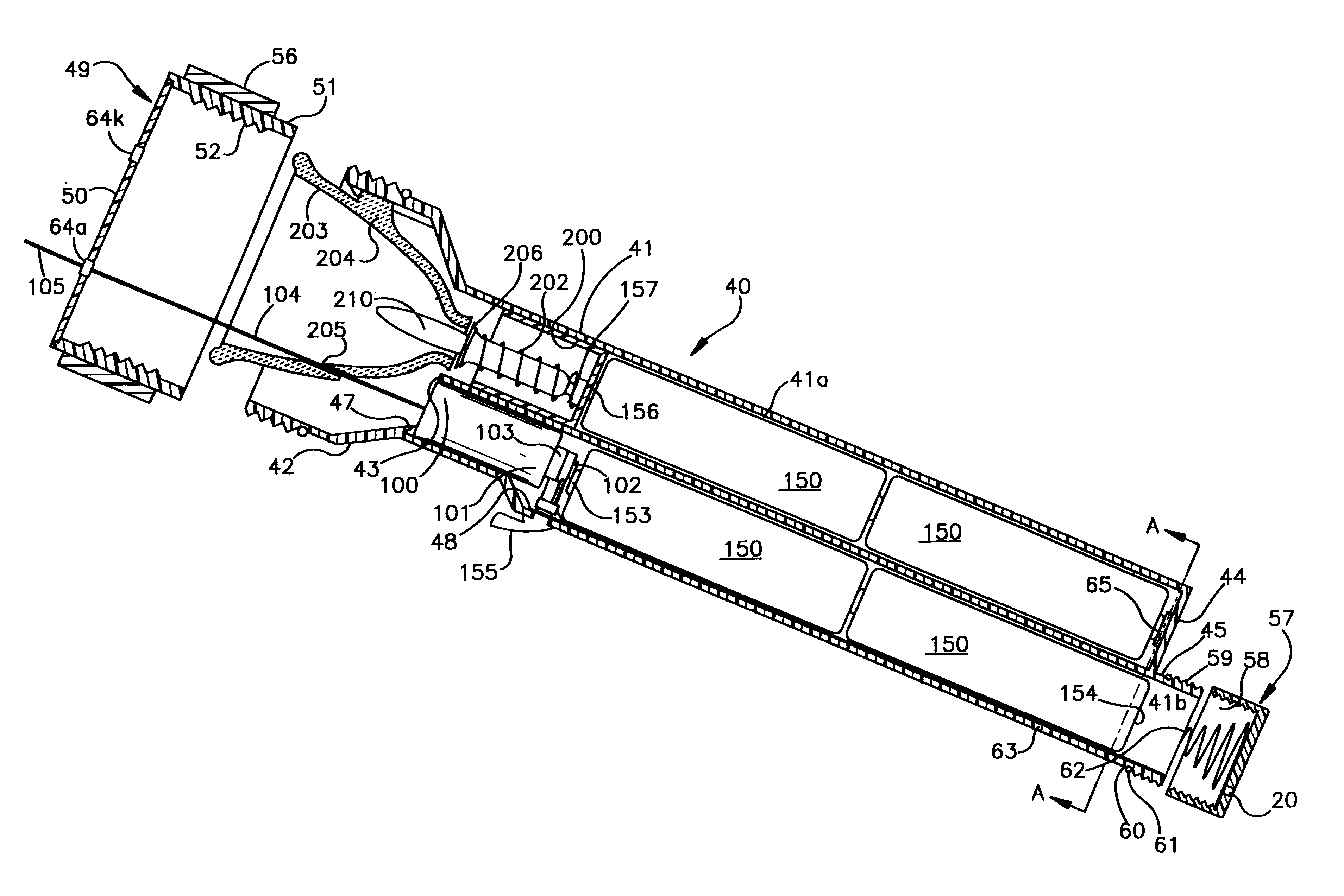
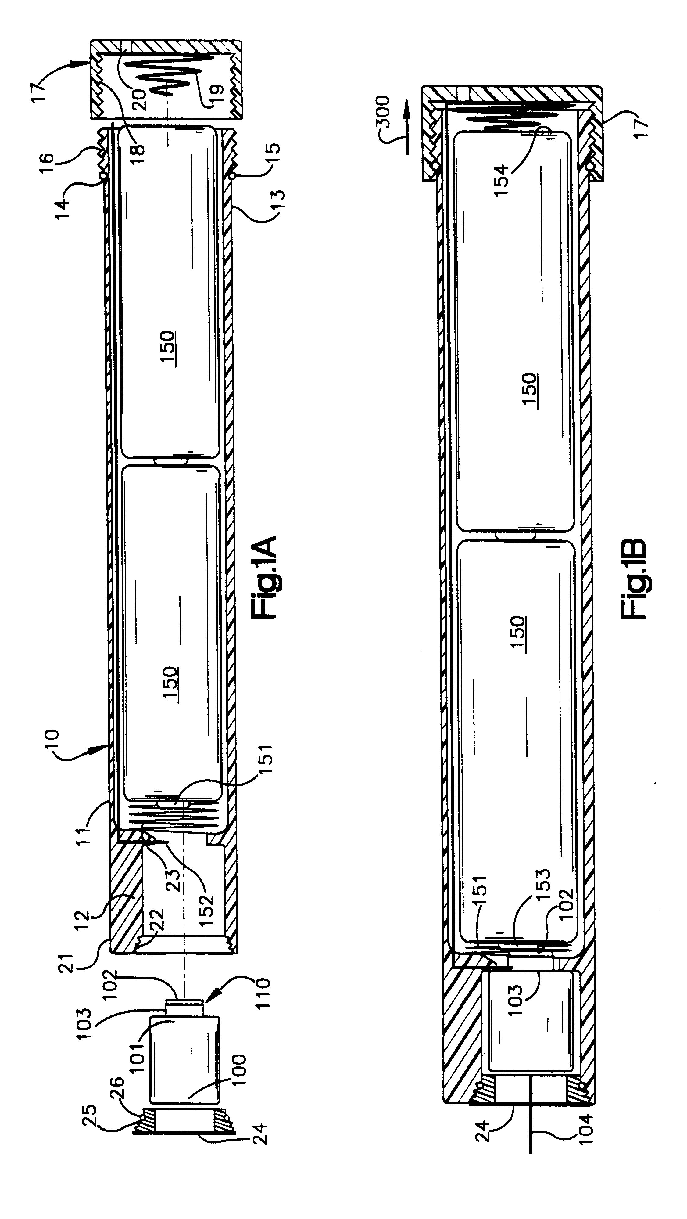
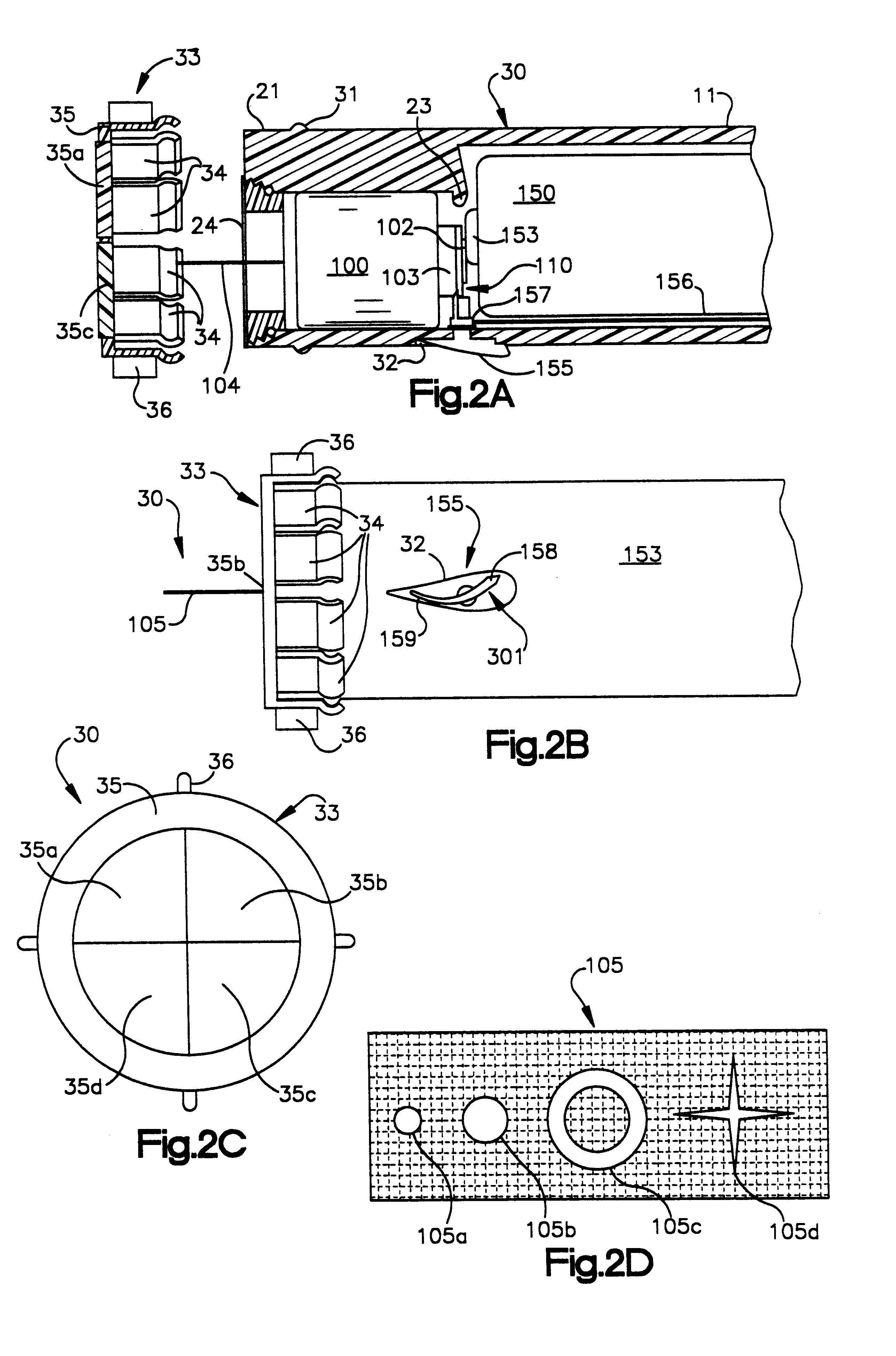
Referring now to the drawings, there is illustrated in FIG. 1A a cut-away assembly side view of the preferred embodiment of the laser light generally designated 10.

The generally tubular housing 11 is of a size and shape which allows the insertion of one or more removable batteries 150, a solid state laser diode 100, (held in place within a circular diode guide 12 formed within the housing), and a front spacing spring 151 for controlling battery 150 contact with the laser emitting diode 100.

The batteries 150 are inserted into the rear of the housing 13. The outer wall of the rear of the housing 13 is circularly groved 14 to secure a rubber or silicone O-ring 15 firmly in place and has circular coarse threads 16. An end cap 17 with internal threads 18 corresponding to the course threads 16 is screwed on to the housing 13 over the O-ring 15 to seal the device 10. The rear-cap 17 also contains a contact spring 19 for controlling battery 150 contact with the laser emitting diode 100 and ...


PUM


Abstract

A novel hand held waterproof or submersible laser illumination device which provides for prolonged precise controlled illumination. The present invention also provides for a combination generalized illumination and selectable precise laser outputs.

Description

1. Technical Field of the InventionThis present invention relates to hand held lighting devices, and more particularly to a novel hand held waterproof or submersible laser light and laser flashlight, for illumination, communication, targeting, presentations, and measurement.2. BackgroundThose experienced with diving will recall that inexpensive underwater communication is normally a combination of writing tablets, hand signals and nods. Watertight flashlights may solve some problems but do not provide the precise highly visible illumination and communication a submersible laser emitting illuminator yields.Watertight flashlights are useful to ensure the integrity and reliability of operation in wet and harsh environments. In the underwater environment the users ability to see clearly, communicate verbally, and dexterity are limited by the breathing equipment and the dampening effect of the water. Also, often in non-underwater environments verbal communication may be restricted or lim...

Claims


Application Information

Patent Timeline
Patent Type & Authority Patents(United States)
IPC IPC(8): F21V31/00F21K7/00F21L4/00F21K99/00F21L4/02
CPCF21K99/00F21L7/00F21V31/00F21Y2101/025F21Y2113/02F21L4/005F21Y2113/20F21Y2115/10F21Y2115/30
Inventor KRIETZMAN, MARK HOWARD
Owner KRIETZMAN MARK HOWARD
Learn More