
Switch device capable of maintaining stable knob operability over long term

a technology of switch device and knob, which is applied in the direction of switch with three operating positions, contacts, enclosure/screen, etc., can solve the problems of undesirable gap and deterioration of the operability of the knob 20

Inactive Publication Date: 2001-02-20
ALPS ALPINE CO LTD
View PDF4 Cites 20 Cited by
  • Summary
  • Abstract
  • Description
  • Claims
  • Application Information

AI Technical Summary

Benefits of technology

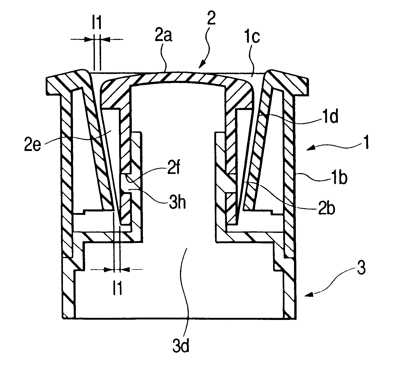
As described above, a switch device according to the present invention is capable of maintaining stable operability of the finger grip portion (knob) over a long period of time because the finger grip portion is housed within the concave portion of the panel such that the side wall of the finger grip portion runs parallel to the inclined wall of the panel, whereby a gap dimension in the concave portion between the side wall and the inclined wall on the opening side can be formed narrow, and therefore, there is no possibility that any foreign matter such as dust enters this gap.Also, since the gap dimension is a comparatively small dimension, this narrow gap provides a switch device desirable also in view of a fine appearance.Also, a switch device according to the present invention is provided with a concave portion surrounded by edge portions on the side wall of the finger grip portion (knob), and since the weight can be saved by the volume of this concave portion, this switch device can be reduced in weight, and further, the material cost for the amount can be saved, thus making it possible to provide a low-cost switch device.In addition, as described above, the edge portion of the side wall of the finger grip portion and the inclined wall of the panel slantingly run in parallel, and the gap dimension is a comparatively narrow dimension, and therefore, this narrow gap provides a switch device desirable also in view of a fine appearance.

Problems solved by technology

Consequently, a gap dimension 12 with the top surface wall 20a of the knob 20 on the side of the panel unit 1a of the panel 1 becomes large, and therefore, there is the problem that when foreign matter such as dust enters this gap, the operability of the knob 20 will be deteriorated.
Also, when the gap dimension is comparatively large, there is the problem that this gap becomes undesirable also in view of a fine appearance.

Method used


Image

  • Switch device capable of maintaining stable knob operability over long term
  • Switch device capable of maintaining stable knob operability over long term
  • Switch device capable of maintaining stable knob operability over long term

Examples


Embodiment Construction

With reference to the drawings, the description will be made of a switch device according to an embodiment of the present invention.

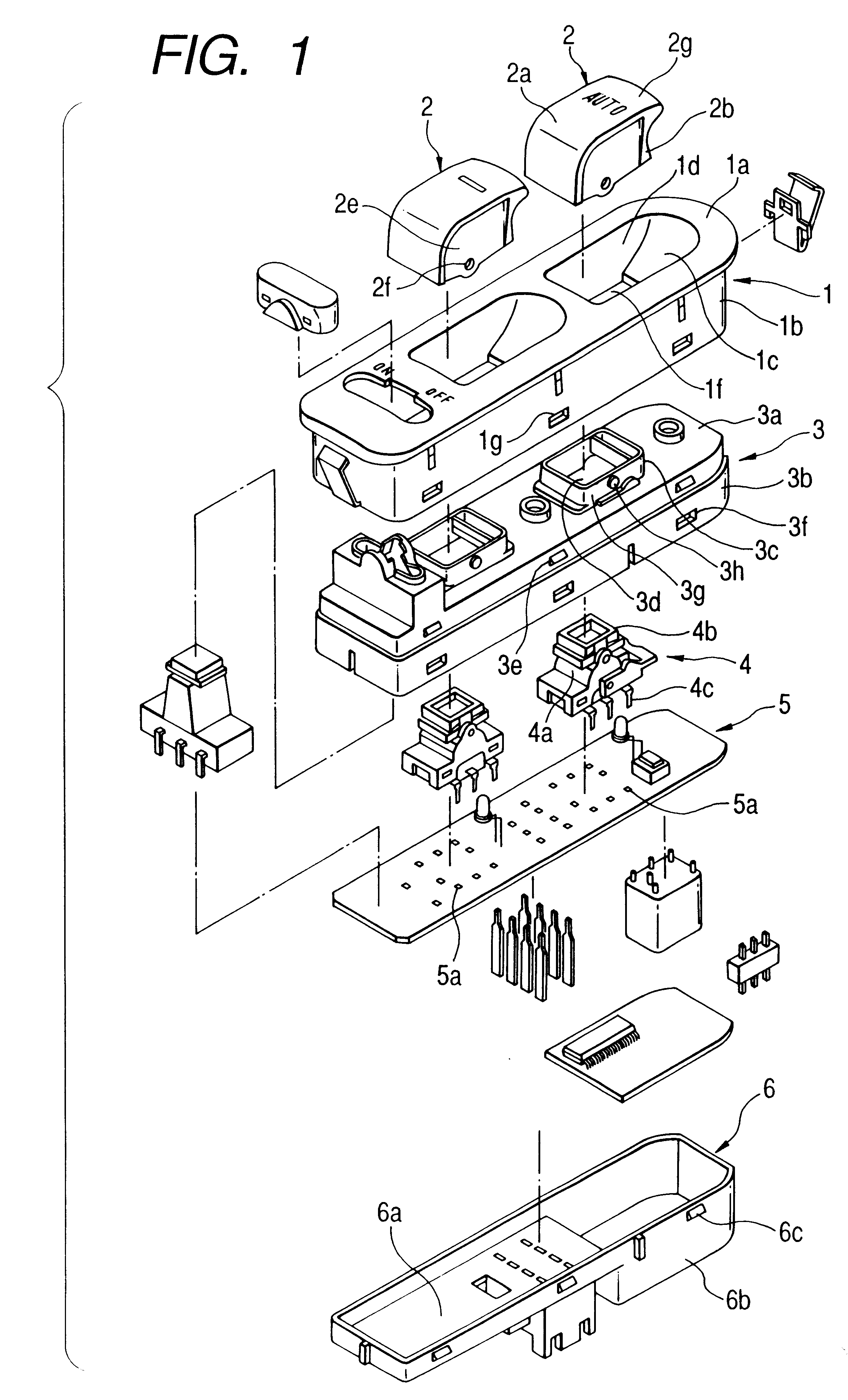
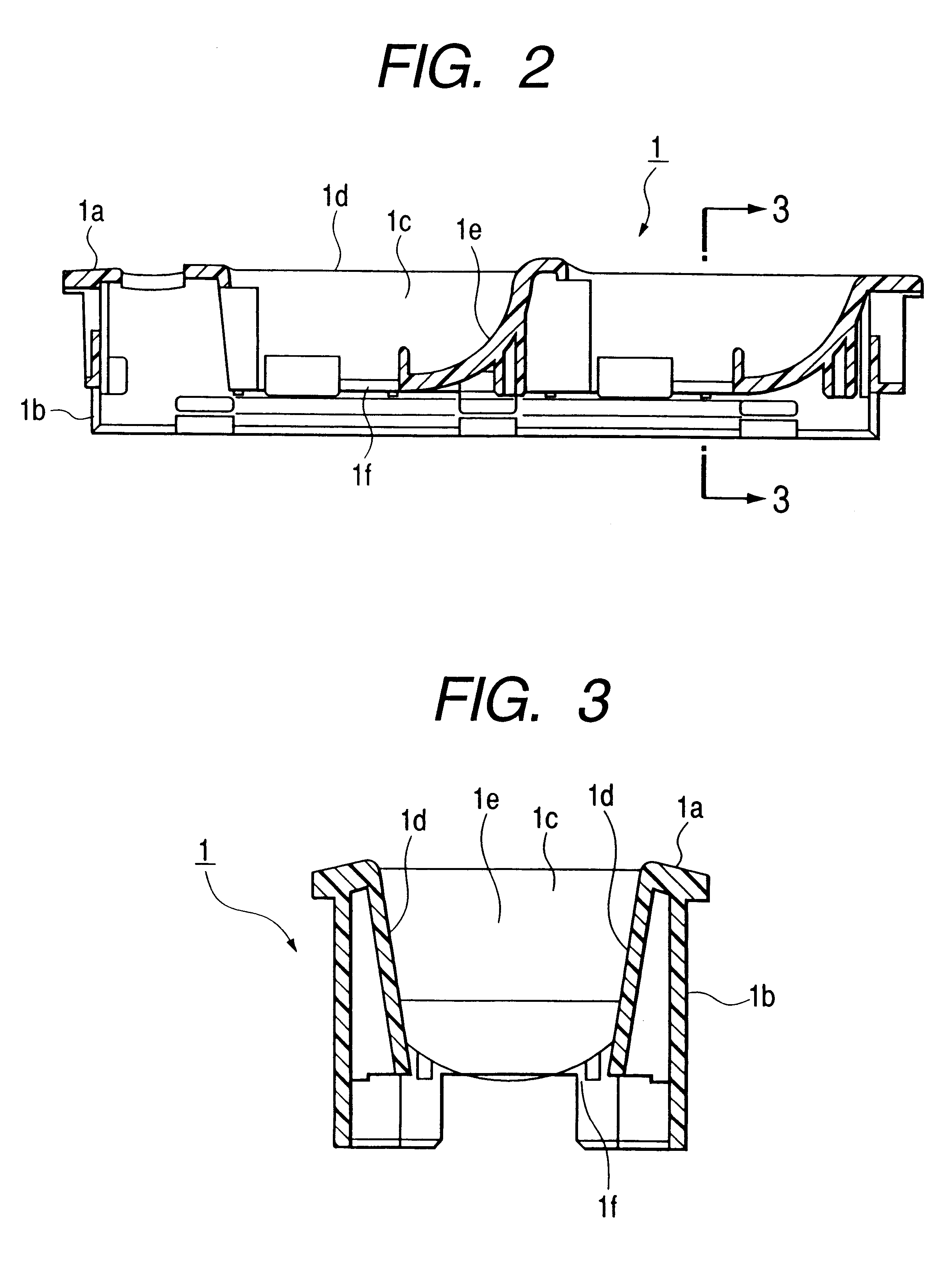
FIG. 1 is an exploded perspective view showing a switch device according to an embodiment of the present invention; FIG. 2 is a sectional view showing a panel of the switch device according to the present invention; FIG. 3 is a sectional view taken on line 3--3 of FIG. 2; FIG. 4 is a perspective view showing a knob of the switch device according to the present invention; FIG. 5 is a sectional view taken on line 5--5 of FIG. 4; and FIG. 6 is a sectional view showing a panel, a knob and a housing of the switch device according to the present invention.

In this respect, portions identical to those in the conventional switch device are designated by the identical reference numerals.

As shown in FIGS. 1 to 6, a switch device according to the present invention is schematically constructed of a panel 1; a plurality of (for example, two) knobs 2 to be housed in t...


PUM


Abstract

A switch device having an excellent external view, capable of maintaining stable operability of a finger grip portion over a long period of time by reducing a gap dimension between a panel and the finger grip portion (knob) of the switch device. The having a panel which has a concave portion provided with a pair of mutually-opposed inclined walls, the tip end sides of which are inclined so as to spread toward the outside, and a finger grip portion of the switch unit arranged within the concave portion, wherein the finger grip portion is constructed of an enclosure consisting of a top surface wall and side walls, wherein a pair of mutually-opposed side walls are inclined such that the distance therebetween becomes narrower toward the opening of the enclosure, and wherein the side walls run in parallel with the inclined wall of the panel.

Description

1. Technical Field of the InventionThe present invention relates to a switch device, and more particularly to a switch device used for opening or closing a window in an automobile-installed power window device.2. Prior ArtWith reference to the drawings, a description will be made of a conventional switch device.FIG. 9 is an exploded perspective view showing a conventional switch device; FIG. 10 is a perspective view showing a conventional knob of the switch device; FIG. 11 is a sectional view taken on line 11--11 in FIG. 10; and FIG. 12 is s sectional view showing a conventional panel, a knob and a housing in the switch device.As shown in FIGS. 9 to 12, the conventional switch device is schematically constructed of a panel 1; a plurality of (for example, two) knobs 20 to be housed in the panel 1; a housing 3 with which the panel 1 is engaged; a switch unit 4 which is housed in the housing 3 and to which the knobs 20 are mounted; a printed circuit board 5 to which the switchunit 4 is...

Claims


Application Information

Patent Timeline
Patent Type & Authority Patents(United States)
IPC IPC(8): H01H21/22H01H21/00H01H3/12H01H23/30
CPCH01H21/22H01H2021/225H01H2229/044H01H2300/01
Inventor SASAKI, MIKIOSOTOOKA, KAZUO
Owner ALPS ALPINE CO LTD
Learn More