Method and system for detecting the end of a tape within a magnetic tape drive

a magnetic tape drive and tape end technology, applied in the field of information retrieval methods and systems, can solve the problems of high pantocam field replacement rate, inefficient use of thinner tapes, undue wear and tear

Inactive Publication Date: 2001-02-13
IBM CORP
View PDF5 Cites 14 Cited by
  • Summary
  • Abstract
  • Description
  • Claims
  • Application Information

AI Technical Summary

Problems solved by technology

Such techniques function properly with thick "beefy" tape, but is inefficient when utilized with thinner tape.
Utilizing these old techniques for detecting the end of the tape causes undue wear on the pantocam linkage, contributing to high pantocam field replacement rates.
In addition, too much stress is placed on thinner tape when utilizing such end-of-tape detection techniques.
In the process of reading or writing data on a magnetic tape, an uncertainty in position results from tape stretching and the entrainment of air in the wraps of tape on the reels.
A motion from end to end can result in an uncertainty of several meters of tape.
Consequently, the tape position measured by the counters connected to tachometers on the reel motors can not be used to reliably predict the end of tape.

Method used


Image

  • Method and system for detecting the end of a tape within a magnetic tape drive
  • Method and system for detecting the end of a tape within a magnetic tape drive
  • Method and system for detecting the end of a tape within a magnetic tape drive

Examples


Embodiment Construction

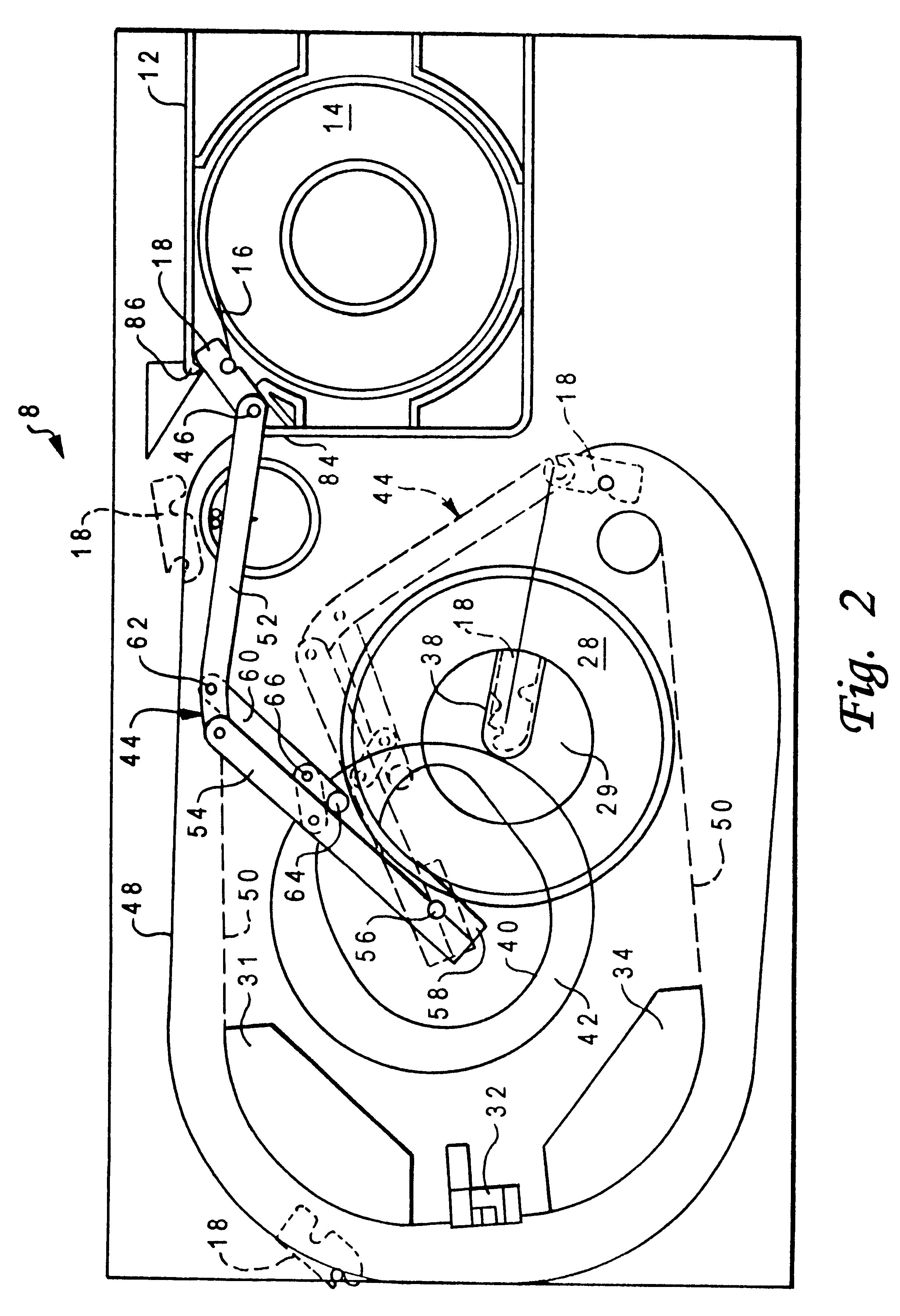
With reference now to the figures and in particular with reference to FIG. 1, there is depicted a schematic diagram of a tape drive system 8 which may be utilized in accordance with a preferred embodiment of the present invention. FIG. 1 is a perspective view of tape drive system 8. Tape drive system 8 includes a base plate 10 on which various standard components of a magnetic tape transport may be mounted. A supply cartridge 12 is replaceable and includes a reel 14 of magnetic tape 16. A leader block 18 is disposed externally of the cartridge. The leading edge of magnetic tape 16 is attached to the side of leader block 18.

A drive motor 20 for the supply reel 14 is mounted beneath base plate 10 so that its shaft extends normal to the surface and slightly above surface 22 of base plate 10. The motor shaft is provided with a suitable clutching arrangement which permits the motor to be coupled to the hub of the supply reel 14 by movement of the cartridge 12 in a direction normal to the...


PUM


Abstract

A method and system for detecting the end of a tape within a tape drive system, wherein the tape drive system includes a take-up reel and a supply reel upon which the tape is wound. The tape is driven through the tape drive system at a closed loop velocity. A tension transducer located in a path of the tape is utilized to monitor a tension associated with the tape while the tape is being driven through the tape drive system at the closed loop velocity. The tension transducer is utilized to detect the end of the tape. The take-up reel is then moved through a predetermined arc of rotation, in response to a cessation of the driving of the tape through the tape drive system. A confirmation is then provided that the end of tape has been detected, in response to a particular output of the tension transducer. Verification that the end of the tape has been achieved is provided, in response to an output of a tachometer attached to the take-up reel, while moving the take-up reel through a predetermined arc of rotation, if the output of the tachometer is at least equal to a predetermined threshold parameter.

Description

1. Technical FieldThe present invention relates in general to information-retrieval methods and systems. In particular, the present invention relates to magnetic media. More particularly, the present invention relates to magnetic tape drive systems. Still more particularly, the present invention relates to methods and systems for detecting the end of magnetic storage tapes within magnetic tape drive systems.The present invention is additionally related to motion and positional control of magnetic tape in a reel-to-reel tape drive. Such control of magnetic tape motion and position in reel-to-reel tape drives is described in detail in U.S. Pat. No. 4,015,799 and U.S. Pat. No. 4,125,881, both assigned to the assignee of this application and incorporated herein by reference in their entireties.2. Description of the Related ArtMagnetic tape drives are commonly utilized for controlling the movement of magnetic tape past a read or write head, and / or to allow automatic rewinding. Magnetic t...

Claims


Application Information

Patent Timeline
IPC IPC(8): G11B15/093G11B15/05G11B15/46G11B15/54G11B15/66G11B15/67
CPCG11B15/093G11B15/54G11B15/67
Inventor CHLIWNYI, ALEX
Owner IBM CORP
Why Eureka
Try Eureka