
Lateral File Locking System

a locking system and file cabinet technology, applied in the direction of building locks, construction, construction fastening devices, etc., can solve the problems of increasing the cost and complexity of cabinet manufacturing

Inactive Publication Date: 2001-02-13
LASALLE BANK NAT ASSOC
View PDF29 Cites 23 Cited by
  • Summary
  • Abstract
  • Description
  • Claims
  • Application Information

AI Technical Summary

Benefits of technology

The present invention overcomes the disadvantages of the prior known file cabinets by providing a simple locking system which engages the individual file drawer or door while also blocking the interlocking mechanism of the cabinet to control opening of the drawers.
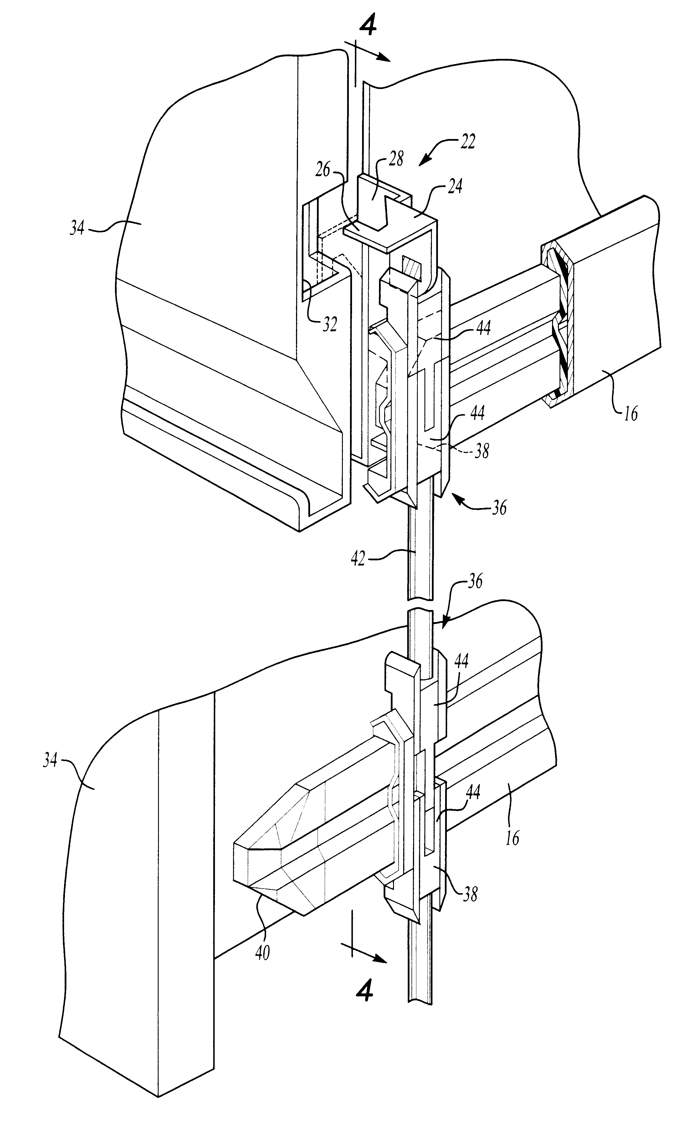
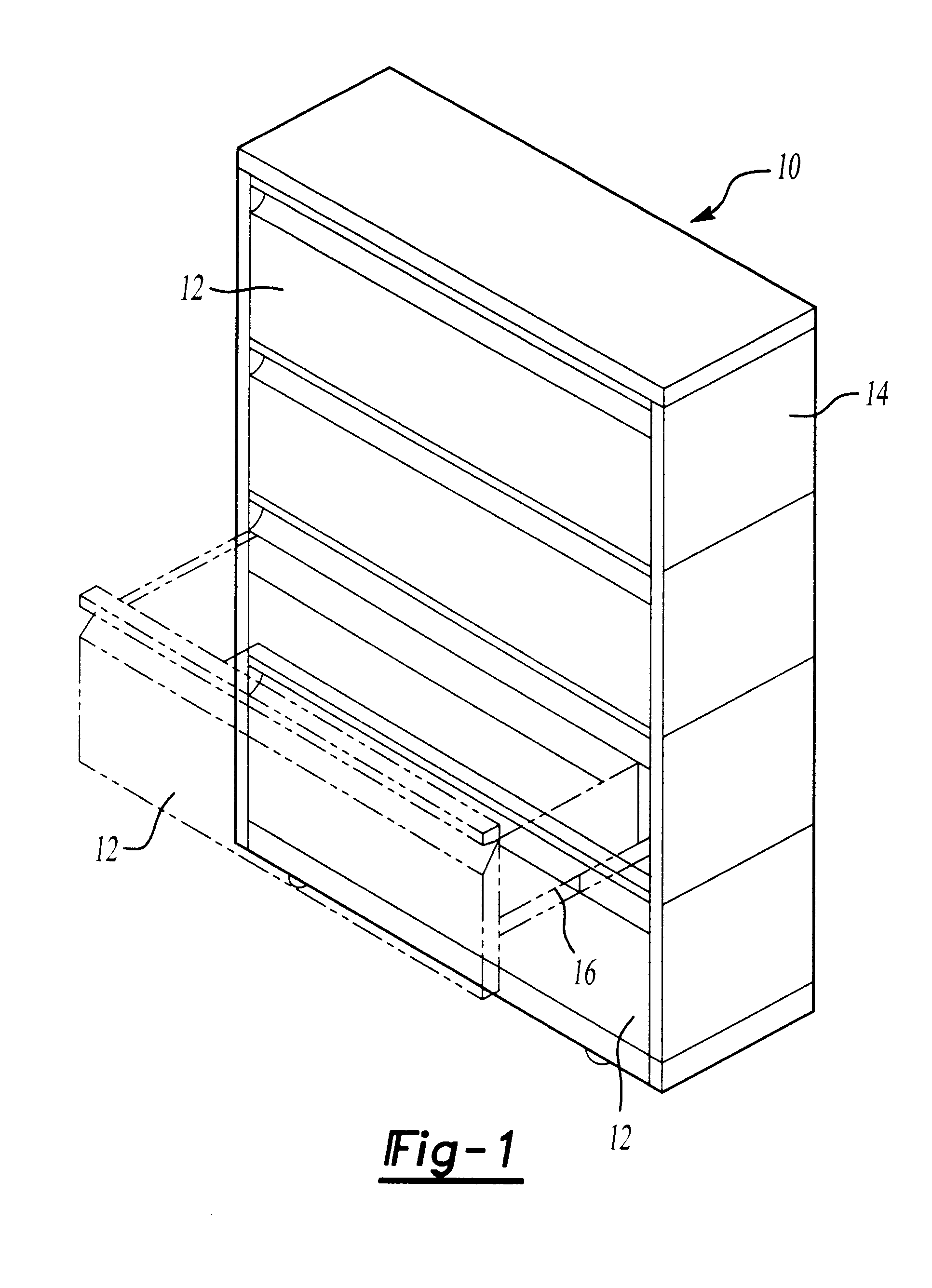
The file cabinet of the present invention incorporates a plurality of file drawers positioned vertically within the cabinet for individual extraction from the cabinet. The drawers ride on a slider assembly for simple movement into and out of the cabinet. The locking system is incorporated into the side wall of the cabinet for engagement with the individual drawers for locking the entire cabinet preventing extraction of any of the drawers. The lock assembly is a single cam lock which hooks into a front panel of the uppermost drawer and engages the interlocking mechanism of the cabinet thereby preventing the other drawers from being opened.
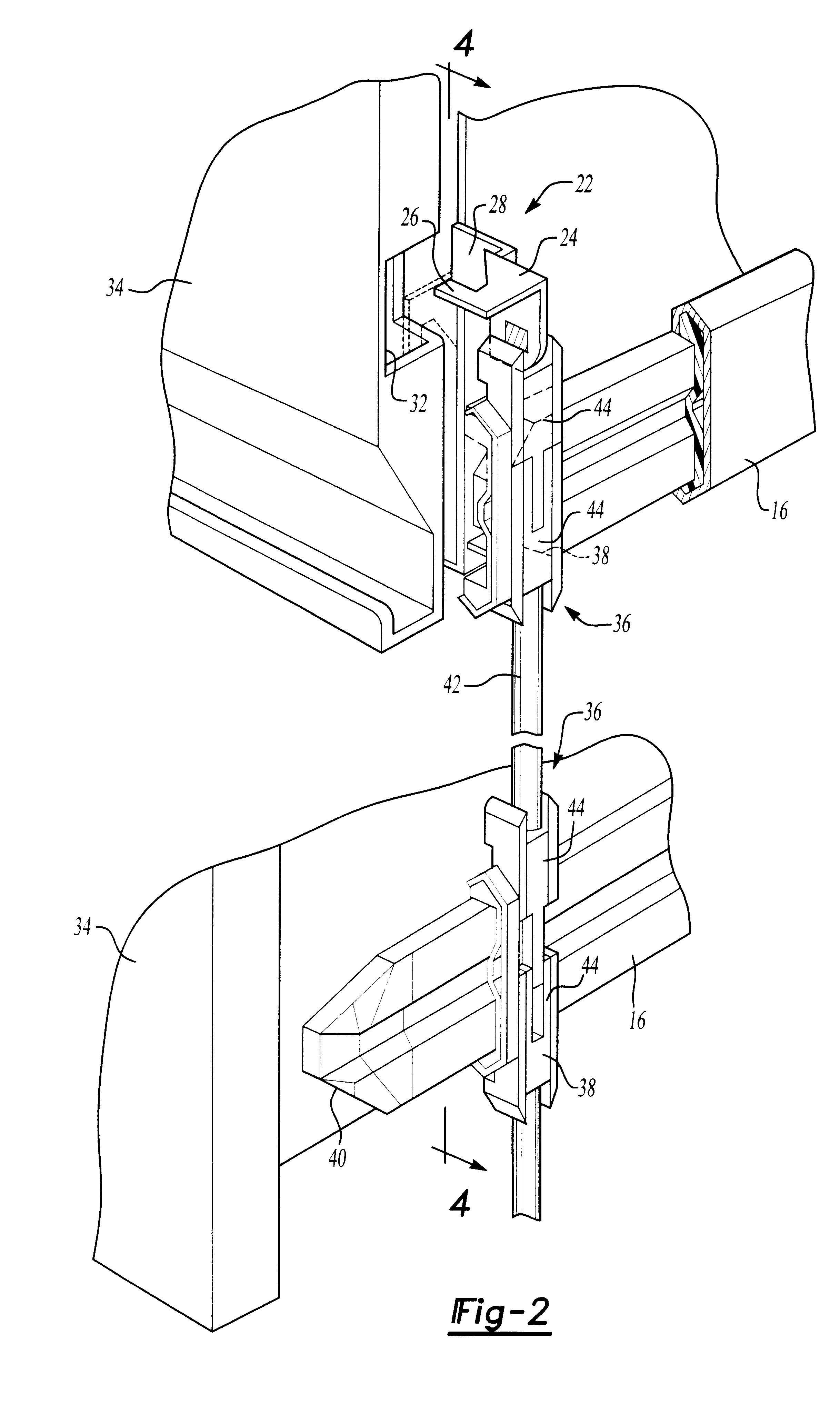
The locking assembly includes a key-operated spindle rotatable within the cabinet wall. Mounted to the rotatable spindle is a lever hook which is movable between an unlocked position and a locked position. The lever hook includes a hook and an end-plate. In the locked position the hook is inserted into an aperture of the front panel of the cabinet while the end plate engages the interlocking mechanism preventing extraction of the drawers. The interlocking mechanisms controls movement of the drawers when one of the drawers has been pulled out. As a result, a simple, single locking mechanism is used to control access to the contents of the file cabinet.

Problems solved by technology

However, the prior known file systems employ interlocking systems which are separate from the overall locking assembly for the cabinet.
The increased part requirements for such a separate locking system increases the costs and complexity of manufacturing of the cabinet.

Method used


Image

  • Lateral File Locking System
  • Lateral File Locking System
  • Lateral File Locking System

Examples


Embodiment Construction

Referring first to FIGS. 1 and 2, there is shown two embodiments of a filing cabinet 10 incorporating a locking system embodied in the present invention. The filing cabinet 10 is a lateral file cabinet with a plurality of selectively extractable file drawers 12. The file drawers 12 are positioned in a vertical orientation and are independently selectively movable between a stored position within the cabinet housing 14 and an extended position exteriorly of the housing 14 for access to the contents of the drawer 12. In a well known manner, the individual drawers 12 are supported on a slider assembly 16 which facilitate lateral movement of the drawer 12 into and out of the cabinet housing 14. The embodiment of FIG. 2 includes four extractable file drawers 12 for storage of files and records. In place of the top drawer, the embodiment of FIG. 1 includes a flip door 18 to provide selective access to the interior storage area 20 at the top of the cabinet 10. Both embodiments of the file ...


PUM


Abstract

A locking system for a file cabinet which prevents opening of more than one drawer of the cabinet. The locking system includes a camming system which blocks opening of any secondary drawers after a first drawer has been opened. A rotatable cam having a hook mounts to an individual lock lever. The hook engages an opening in the file drawer or door to prevent retraction while also blocking the interlocking mechanism for the file drawers.

Description

I. Field of the InventionThis invention relates to a locking system for a file cabinet and, in particular, to a rotatable cam lock which engages the individual drawer and simultaneously blocks the interlocking mechanism of the file system.II. Background of the InventionFile systems typically include a plurality of drawers or cabinet doors positioned in a vertical arrangement to maximize storage space. In the case of drawers, the individual drawers are slidably extractable from the cabinet to allow access to the interior contents of the drawer. A flip up door may be employed to enclose the individual storage units facilitating access from the front of the unit rather than the top as in a drawer. In order to maintain stability of the cabinet, it is preferred that only one drawer be allowed to be extracted at a time. Interlocking systems have long been employed which prevent multiple drawers from being opened in such cabinets. However, the prior known file systems employ interlocking s...

Claims


Application Information

Patent Timeline
Patent Type & Authority Patents(United States)
IPC IPC(8): E05B65/46E05B65/44E05B65/463
CPCE05B65/46E05B65/463
Inventor KREI, CHRISTOPHER J.
Owner LASALLE BANK NAT ASSOC
Learn More