Fluid power rotary drive device

a rotary drive and flue-type technology, which is applied in the direction of friction gearings, belts/chains/gearings, mechanical instruments, etc., can solve the problems of lack of any possibility of presetting intermediate positions of the output drive parts, and the field of application is limited to certain uses, so as to avoid jitter and effectively choke the spent air

Inactive Publication Date: 2001-01-09
FESTO AG & CO KG
View PDF12 Cites 10 Cited by
  • Summary
  • Abstract
  • Description
  • Claims
  • Application Information

AI Technical Summary

Benefits of technology

It is furthermore an advantage if on leaving the positioning setting of the abutment unit there is an effective choking of spent air. This renders possible controlled movement of the abutment unit, when the output drive part is moved out of the intermediate position, jitter being avoided.

Problems solved by technology

A disadvantage in the case of rotary drive devices known to the assignee is the absence of any possibility of presetting intermediate positions of the output drive part.
This means that the field of application is limited to certain uses.

Method used


Image

  • Fluid power rotary drive device
  • Fluid power rotary drive device
  • Fluid power rotary drive device

Examples


Embodiment Construction

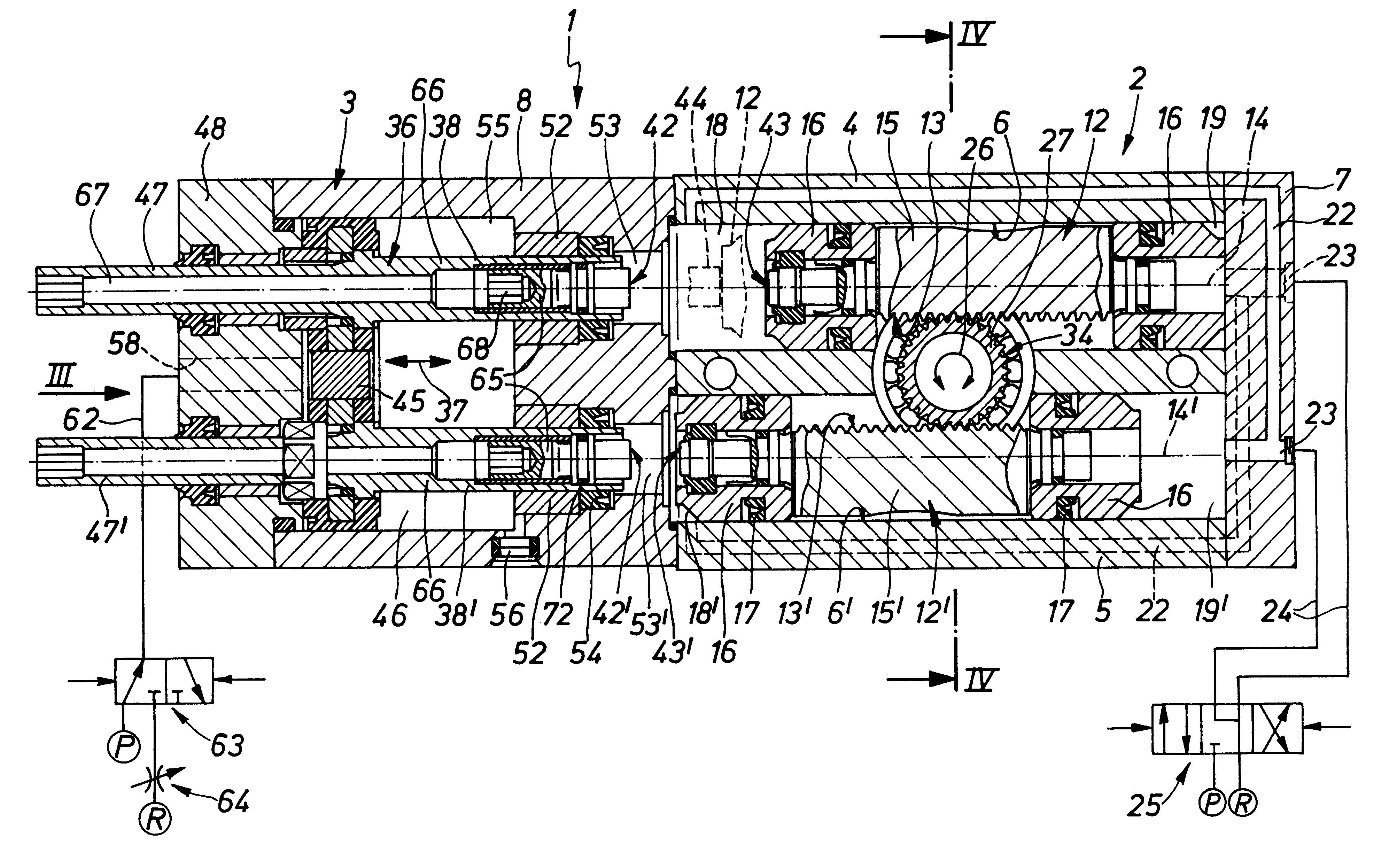
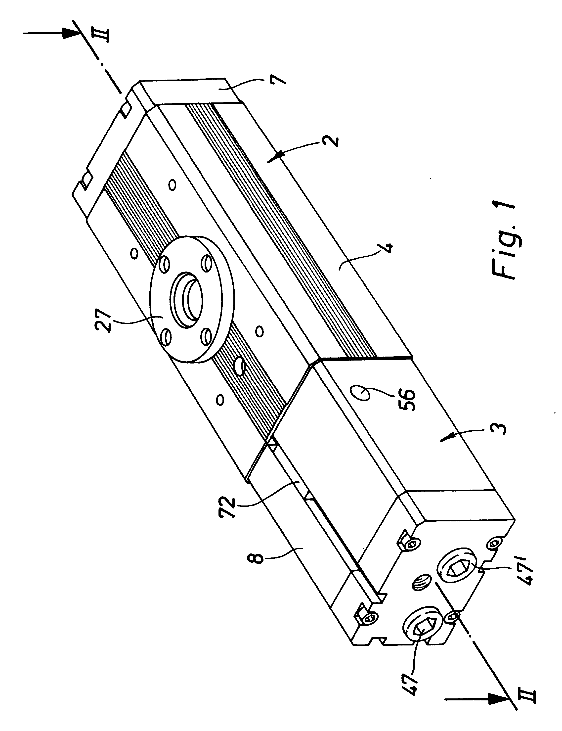
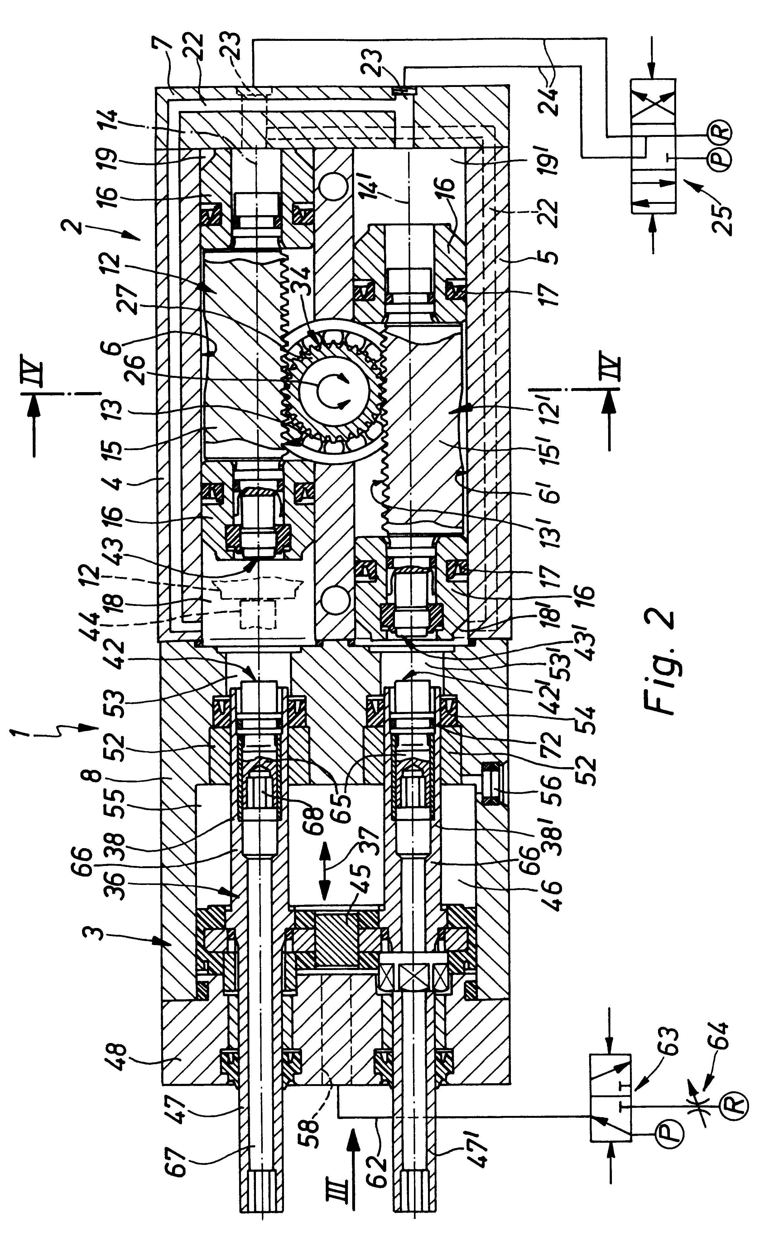
The rotary drive device generally referenced 1 in the drawings comprises a drive module 2 and a positioning module 3 detachably but securely connected with same. The general structure of the drive module 2 may be according to the prior art and the novelty as such of the invention is in relation to the positioning module 3 and its cooperation with the drive module 2.

The drive module 2 contains a first longitudinal housing 4, preferably with a cube-like outline. As regards details, it has an elongated base section 5, which in the longitudinal direction has two adjacently placed piston receiving spaces extending through it. The piston receiving spaces 6 and 6' are closed at one axial end in a sealing manner by a terminating cover 7 to the rear on the base section 5. The opposite front closure is ensured by the positioning module 3, whose housing, in what follows referred to as the second housing 8, is placed on the front end side of the base section 5 and is secured by means of screws,...


PUM


Abstract

A fluid power rotary drive device, which possesses two oppositely moving drive pistons and an output drive part in mesh with the same. With the aid of a position presetting means it is possible to preset an intermediate position of the output drive part. For this purpose an abutment unit is provided, which has two abutment parts arranged as an axial extension of the two drive pistons. The abutment unit is able to be moved relatively to the drive piston into a positioning setting, in which the two abutment parts are both in engagement with the respectively associated drive piston, something which corresponds to the desired intermediate position.

Description

The invention relates to a fluid power rotary drive device comprising a rotatably mounted output drive part, which has at least one ring of teeth, with which rack means, arranged on two juxtaposed drive pistons, are in engagement, the drive pistons being adapted to be oppositely moved by fluid actuation in two mutually parallel directions in order to cause a rotary movement of the output drive part between two end positions.THE PRIOR ARTOwing to the presence of two drive pistons rotary drive of this type are referred to as double piston rotary drives. Their output drive part, which is generally designed in the form of a solid or hollow shaft, extends through and between the two drive pistons, with which it is engaged by gear teeth at a diametrally opposite peripheral position. By means of suitable fluid actuation it is possible for the drive pistons to be driven to perform an oppositely directed linear movement, something which in accordance with the selected direction of travel res...

Claims


Application Information

Patent Timeline
Patent Type & Authority Patents(United States)
IPC IPC(8): F15B11/12F15B15/00F15B11/00F15B15/08F03C1/02F03C1/00F15B15/06F15B15/24F16H19/00
CPCF03C1/02F15B11/123F15B15/065
Inventor STOLL, KURTWAGNER, ALBRECHTPFEIFFER, DIETMAR
Owner FESTO AG & CO KG
Why Eureka
Try Eureka