Counting device for the remote counting of stacked objects in a stack of thin objects, as well as a counting method using a counting device

a technology of a counting device and a stack of thin objects, which is applied in the direction of measurement devices, instruments, material analysis, etc., can solve the problems of faulty counting, complex construction of the mechanical part of the device, and general poor reflection properties of the material edges, so as to improve the focal depth of the counting device, the effect of improving the counting devi

Inactive Publication Date: 2000-12-05
FUNCTION CONTROL RES
View PDF7 Cites 6 Cited by
  • Summary
  • Abstract
  • Description
  • Claims
  • Application Information

AI Technical Summary

Benefits of technology

to provide a device of the kind mentioned in the preamble may be mechanically simple and which results in a greater focal depth and is characterized in that said optic means comprise a diaphragm having a diaphragm opening, which diaphragm opening, in relation to the dimensions of the beam of reflected radiation in part of said radiation path between said optical means and said photoelectric detection means, is smaller. Surprisingly, even though the addition of the diaphragm blocks off a significant amount of the reflector of the already sparse light, the results is a marked improvement of the counting device. This is the effect of the greatly improved focal depth of the counting device.

Problems solved by technology

The disadvantage of this method is that a slight change in brightness between the adjacent layers will cause faulty counting.
The reason for there being so little change in brightness between adjacent layers may be that the material edges have generally poor reflection properties, or that the gap between the in themselves evenly reflecting layers, is too narrow.
The disadvantage of the method using the moving sensor is the complex construction of the mechanical part of the device, while the disadvantage of the method using a CCD camera is the relatively high cost of the CCD camera and the processing unit as well as the poor resolution.
The deficient focal depth of the device of the known art has resulted in an increasingly complex counting device and in the addition of extra movements which increase the mechanic complexity of the device.

Method used


Image

  • Counting device for the remote counting of stacked objects in a stack of thin objects, as well as a counting method using a counting device
  • Counting device for the remote counting of stacked objects in a stack of thin objects, as well as a counting method using a counting device
  • Counting device for the remote counting of stacked objects in a stack of thin objects, as well as a counting method using a counting device

Examples


Embodiment Construction

)

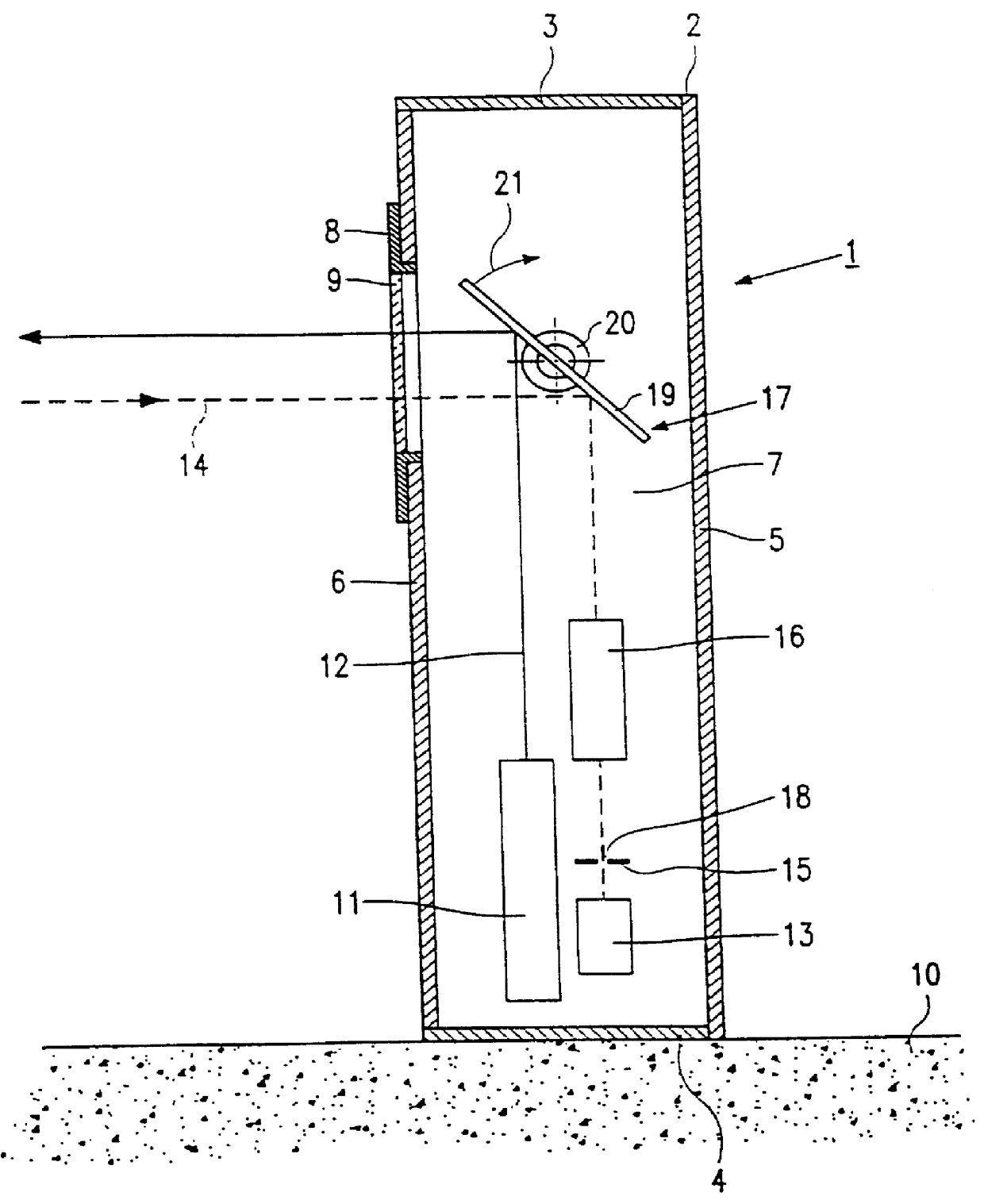
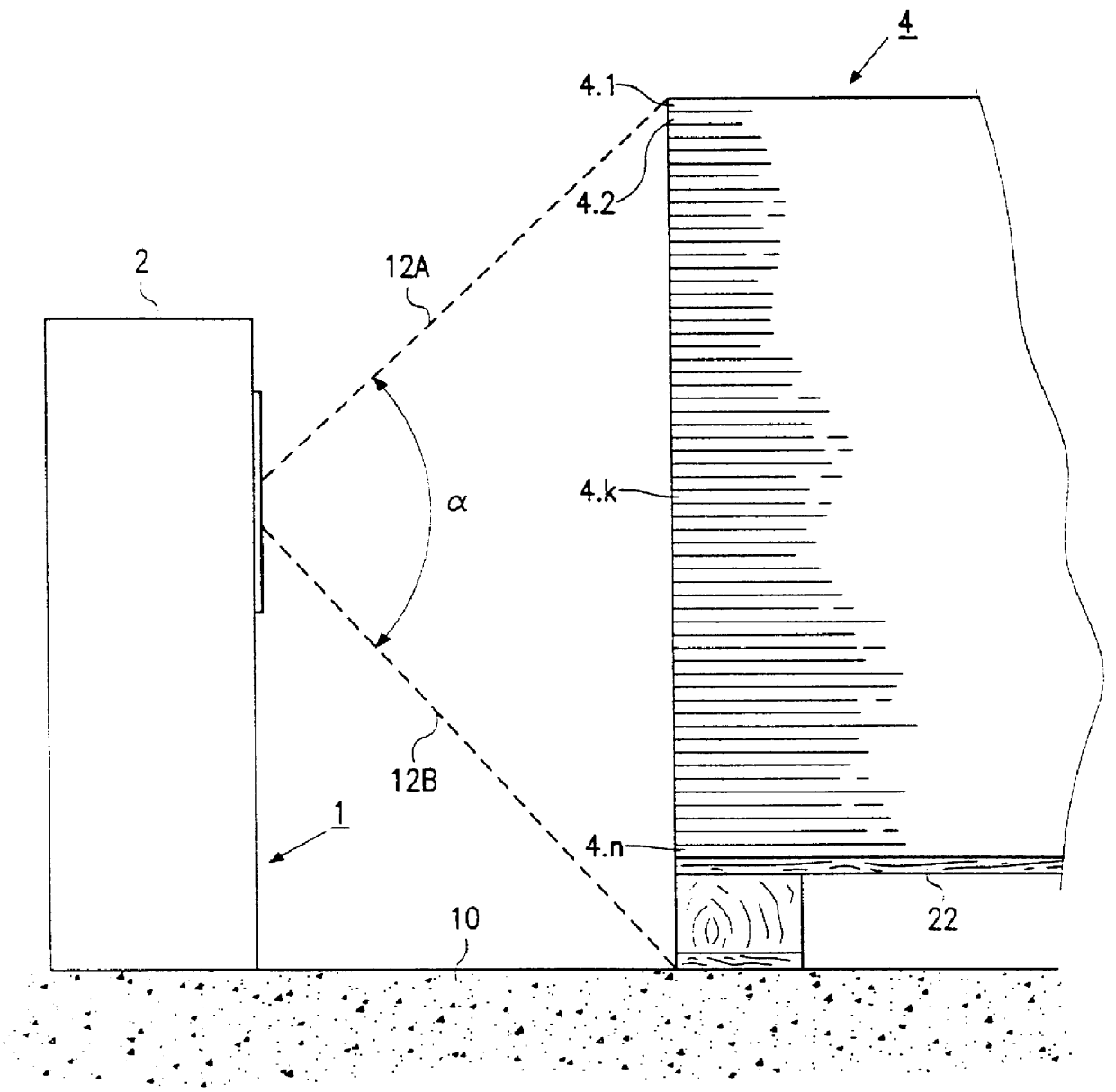
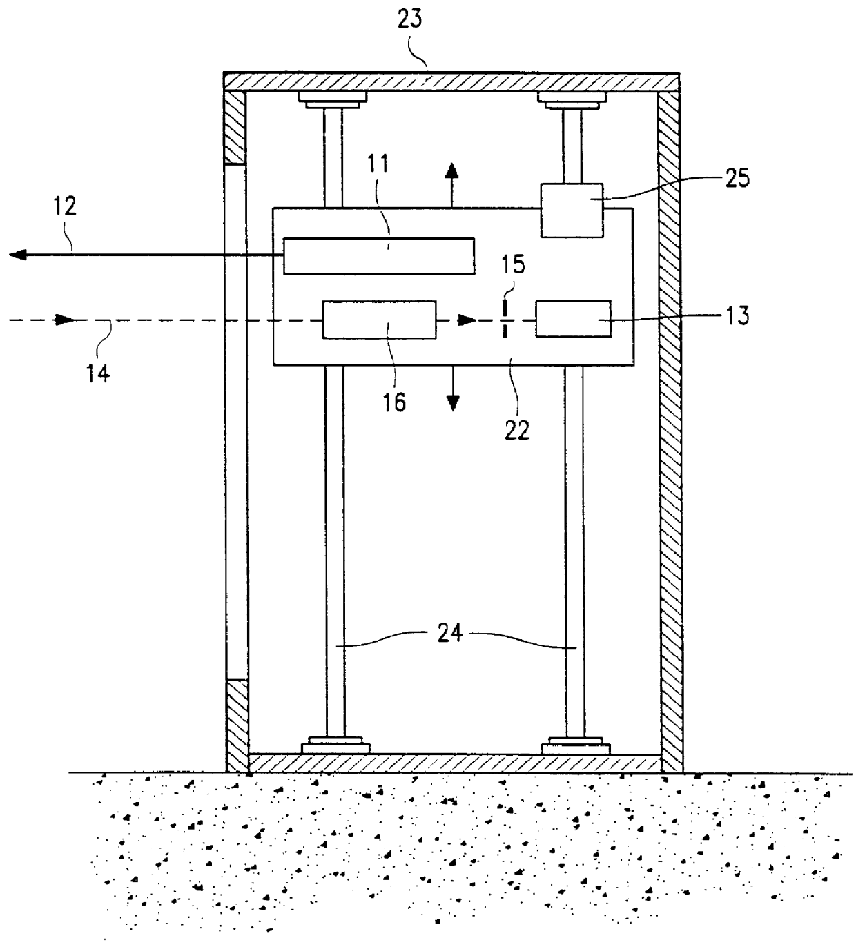
An embodiment of the invention suitable for stationary mounting and which can for instance be used for counting stacked objects such as separate sheets of carton in a stack of carton, is characterized in that the device is provided with a rotatable mirror to make the radiation beam move as a scanning beam over a certain scanning area, and the stack of objects can be placed within said scanning area so that the objects can be scanned by a moving radiation spot produced by the moving scanning beam.

An important consideration with the last-mentioned embodiment is, that if the device is provided with a rotating mirror, an extra difference in optical path length occurs because the distance between the counting device and the top and bottom of the stack is greater than the distance between the middle of the stack and the counting device. The improvement of the focal depth, which is the achievement of the invention, therefore greatly contributes to making the advantageous embodiment possib...


PUM

PropertyMeasurementUnit
diameteraaaaaaaaaa
diameteraaaaaaaaaa
focal distanceaaaaaaaaaa

Abstract

PCT No. PCT/NL96/00446 Sec. 371 Date Jul. 14, 1998 Sec. 102(e) Date Jul. 14, 1998 PCT Filed Nov. 13, 1996 PCT Pub. No. WO97/18532 PCT Pub. Date May 22, 1997A counting device that detects intensity differences in reflections coming from stacked thin objects. The device comprises a radiation source generating a radiation beam and a photoelectric detector detecting the intensity differences in the radiation reflected by the objects, and is provided with an optical pathway placed between the objects and the photoelectric detector. The optical pathway comprises a diaphragm having a diaphragm opening which, in relation to the dimension of the beam of reflected radiation reaching the diaphragm, is smaller.

Description

1. Field of the Invention (Technical Field)The invention relates to a counting device for the remote counting of stacked objects in a stack of thin objects such as carton sheets, comprising a radiation source for the generation of a radiation beam, means for moving the radiation beam along the transverse edges of the stacked objects, photoelectric detection means for the detection of the intensity differences in radiation reflected by the irradiated stacked objects, as well as optical means placed between said stacked objects and said photoelectric detection means.2. Background ArtA counting device of the above-mentioned kind for courting a stack of corrugated board is known from the Dutch patent specification No. 167,530 as well as from the U.S. patent specification 3,581,067, referred to therein.The latter patent specification reports that during the vertical scanning of the stack the charges in reflection behaviour occurring between the separate layers are counted. It is the chan...

Claims


Application Information

Patent Timeline
Patent Type & Authority Patents(United States)
IPC IPC(8): G06M1/00G06M1/10G06M9/00
CPCG06M9/00G06M1/101
Inventor VAN OOSTEROM, WILLEM
Owner FUNCTION CONTROL RES
Why Eureka
Try Eureka