Apparatus and method for lobing and thermal-damage control in shoe centerless grinding

a technology of lobing and thermaldamage control, which is applied in the direction of process and machine control, program control, instruments, etc., can solve the problems of manual operation and inaccurate geometries, reducing support stiffness, and introducing more waviness

Inactive Publication Date: 2000-11-14
XINAOMDT TECH
View PDF10 Cites 14 Cited by
  • Summary
  • Abstract
  • Description
  • Claims
  • Application Information

AI Technical Summary

Problems solved by technology

However, there are two problems in shoe centerless grinding which are (1) waviness due to lobing and chatter, (2) thermal-damage resulting from overheat at the contact area between the rear-shoe and workpiece.
(1) The geometric setup is manually operated and not accurate. The workpiece quality depends on the operator's experience.
(2) Pivot-structure of the shoes causes support stiffness reduction and introduces more waviness.
(3) Stiff rear-shoe structure results in full geometric error feedback to the cutting point and heat accumulation in the contact area between the workpiece and the rear shoe.
(4) The process parameter configuration is not effective in suppressing lobing and chatter.
However, there is no approach so far that can provide a lobing-free operation.
Unfortunately a decrease in contact area will cause a lobing problem and a smaller grinding force decreases the productivity.
There has been no effective solution to the lobing and thermal problems in shoe centerless grinding.

Method used


Image

  • Apparatus and method for lobing and thermal-damage control in shoe centerless grinding
  • Apparatus and method for lobing and thermal-damage control in shoe centerless grinding
  • Apparatus and method for lobing and thermal-damage control in shoe centerless grinding

Examples


Embodiment Construction

With reference to the drawings, an embodiment of the present invention will be explained hereinafter.

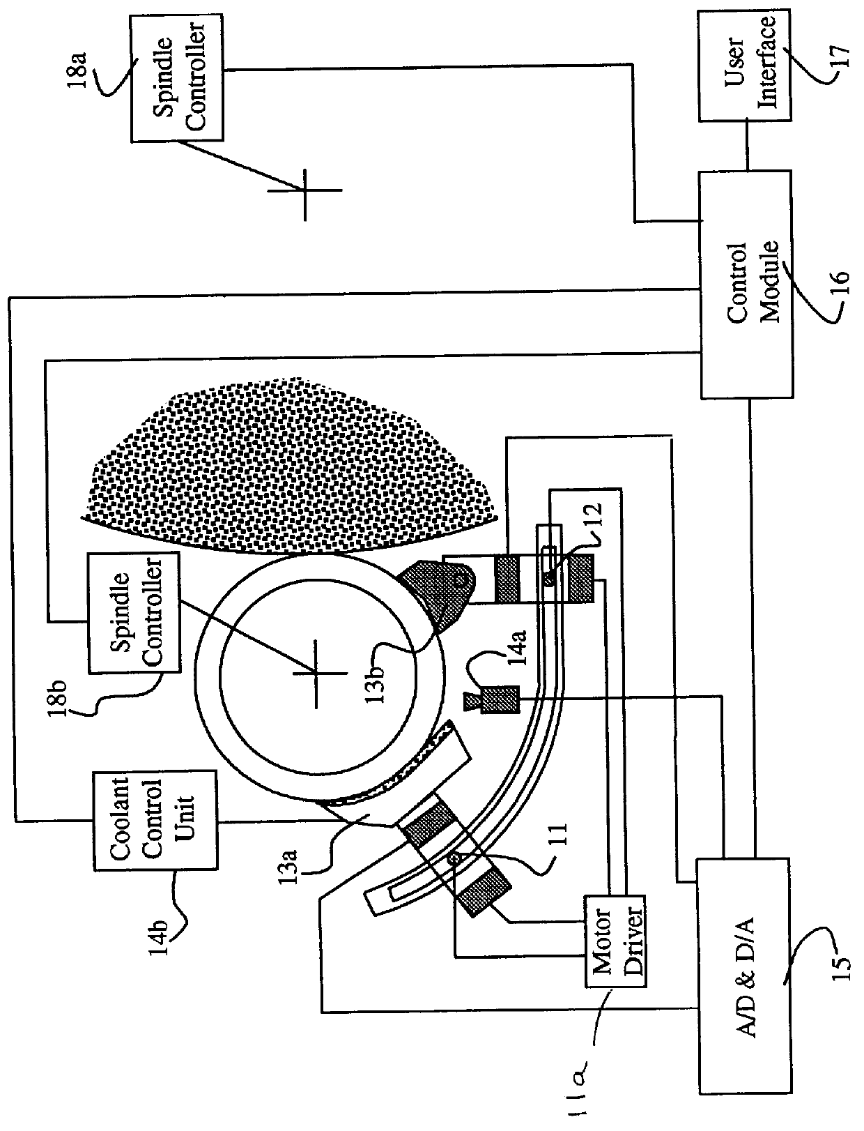
In FIG. 1, an apparatus embodying the present invention is indicated generally by the reference numbers. Number 11 and 12 indicate a pair of motion devices, powered by motor driver 11a, that control the movement of two supporting shoes, and number 13a is a special rear shoe which is used for supporting the workpiece and suppressing the lobing and waviness. Number 13b is the front shoe in centerless grinding. Number 14a is a camera-based monitoring system, which is installed in front of a mounting plate. Number 14b is a control unit for a cooling device. Number 15 is the hardware and software interface of control module number 16. Number 17 is the user interface. Numbers 18a and 18b are the grinding wheel speed controller and the workpiece speed controller respectively.

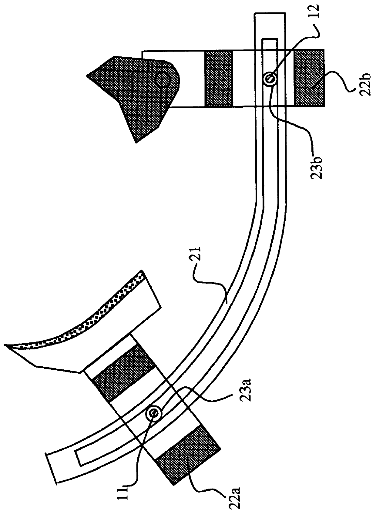
FIG. 2 illustrates the automatic shoe setup device in the apparatus of FIG. 1, which includes

1. Two step motors 11 an...


PUM


Abstract

A control system by which, the lobing and thermal-damage on a component surface will be eliminated and a component of a circular cross-section is capable of being ground with ultra-precision and high quality surface finish. The system includes (i) an automatic controlled supporting device, by which the periphery support of circular component of any size is auto-formed in a most stable work-holding condition; (ii) a flexible rear-shoe with active filtering mechanism, by which the high frequency lobing will be removed and the heat generated in the contact area between the workpiece and rear-shoe will be reduced by the self-lubrication of rear-shoe; (iii) an on-line vision-based temperature monitoring and control device, by which the overheat on the workpiece is controlled; (iv) an on-line phase precession lobing control algorithm, by which the lobing will be effectively suppressed in a rounding process.

Description

This invention is related to a device for lobing and thermal-damage control in shoe centerless grinding. More particularly, to such apparatus wherein the lobing and thermal-damage on the component surface will be eliminated and a component of circular cross-section can be ground with ultra-precision and high quality surface finish in centerless grinding.BACKGROUND OF INVENTIONShoe centerless grinding is a widely used process for the finishing of precision cylindrical components. However, there are two problems in shoe centerless grinding which are (1) waviness due to lobing and chatter, (2) thermal-damage resulting from overheat at the contact area between the rear-shoe and workpiece. Current shoe centerless grinding machine applied in industry can not resolve these problems due to the following reasons:(1) The geometric setup is manually operated and not accurate. The workpiece quality depends on the operator's experience.(2) Pivot-structure of the shoes causes support stiffness re...

Claims


Application Information

Patent Timeline
Patent Type & Authority Patents(United States)
IPC IPC(8): B24B49/12B24B49/00B24B5/00B24B5/307B24B49/14
CPCB24B5/307B24B49/12B24B49/14G05B2219/49319G05B2219/37563G05B2219/41115G05B2219/37426
Inventor SUN, YUNQUANGAN, ZHONGXUE
Owner XINAOMDT TECH
Why Eureka
Try Eureka