Modular air tank assembly

a technology of air tanks and modules, applied in the direction of tank vehicles, transportation and packaging, transportation items, etc., can solve the problems of affecting the installation complexity and other issues

Inactive Publication Date: 2000-07-04
INT TRUCK & ENGINE CORP CANADA
View PDF2 Cites 23 Cited by
  • Summary
  • Abstract
  • Description
  • Claims
  • Application Information

AI Technical Summary

Problems solved by technology

This installation complexity was also hindered by the fact that the tank to tank connections had to be made up in an awkward fashion under the vehicle.

Method used


Image

  • Modular air tank assembly
  • Modular air tank assembly
  • Modular air tank assembly

Examples


Embodiment Construction

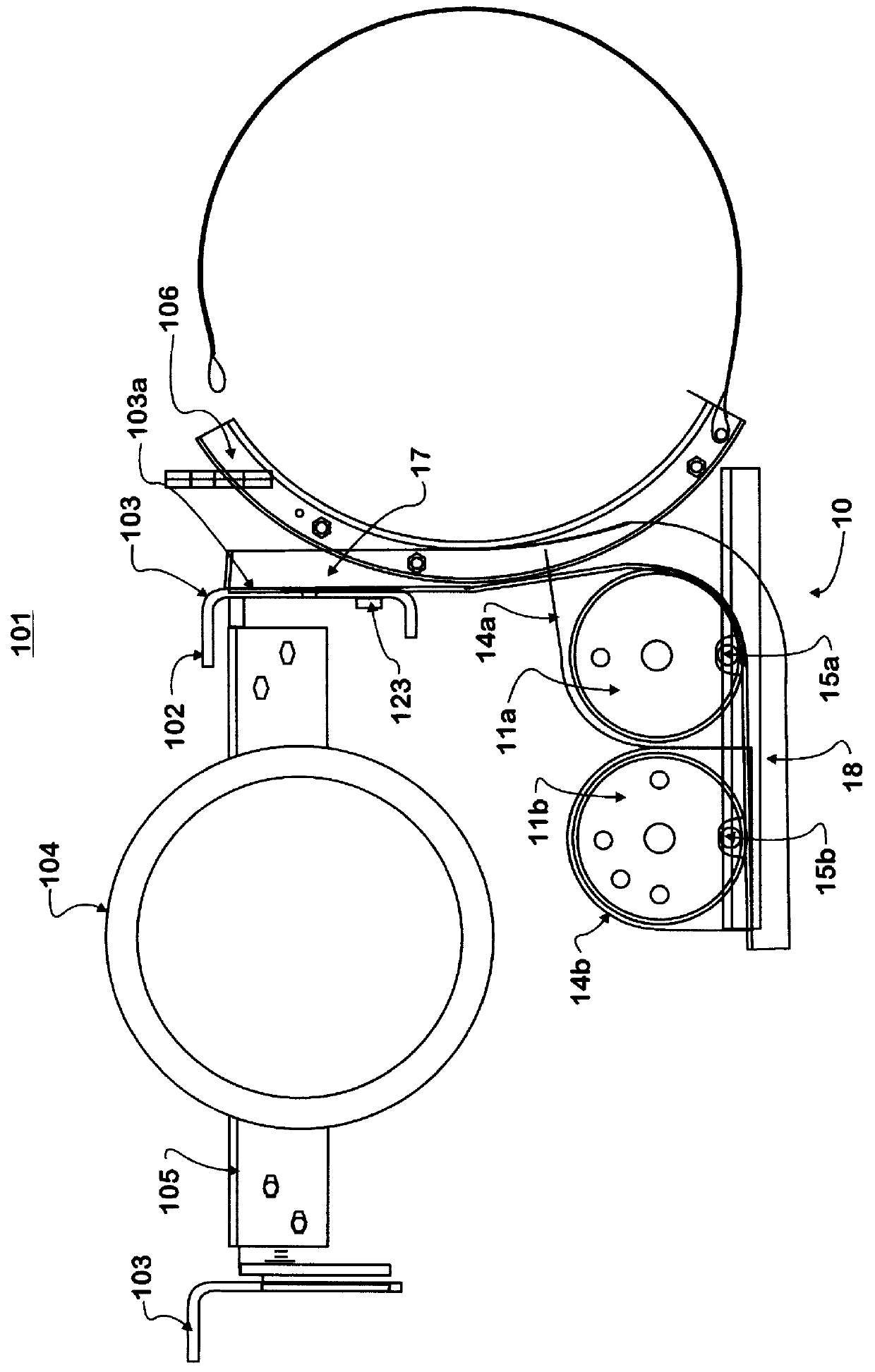
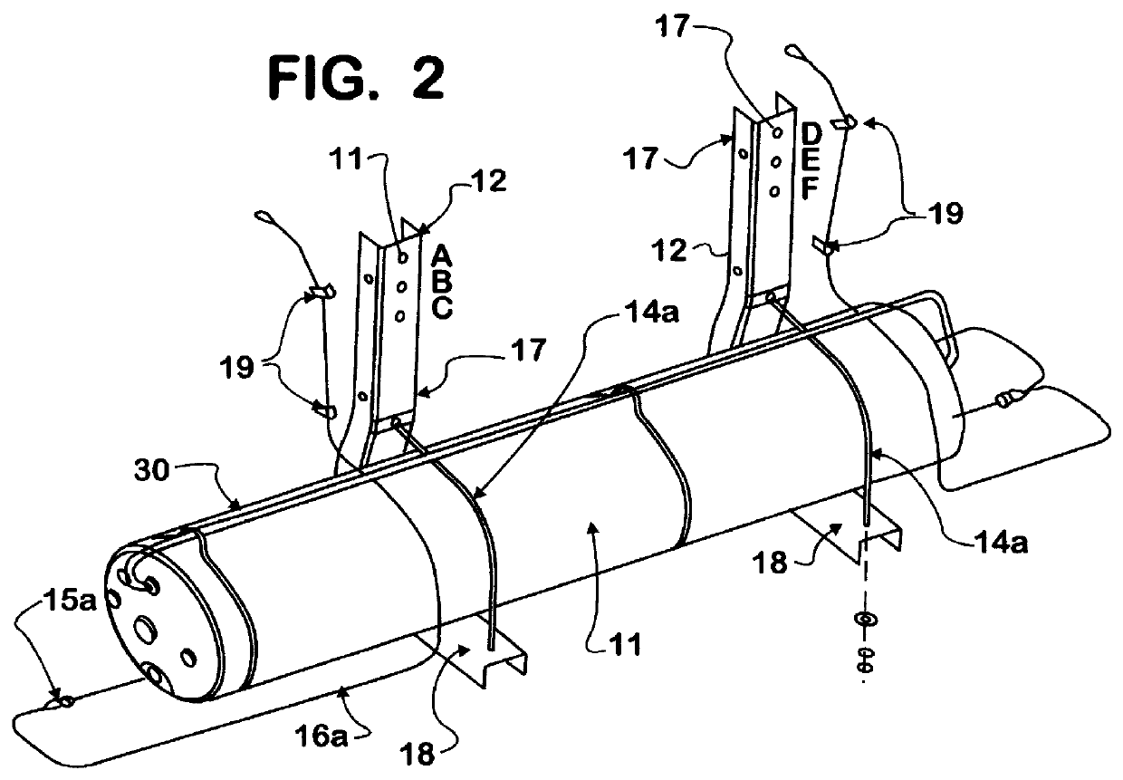
There is shown in FIGS. 1 to 6, a modular air tank assembly 10 for a mobile vehicle 101, such as a heavy duty highway tractor trailer truck. FIGS. 7 to 12 show an assembly jig 50 that may be used in the process of assembling the modular air tank assembly 10 and an assembly tool 60 for installing the modular air tank assembly 10 to the vehicle 101.

The vehicle 101 has a chassis 102 comprised of two generally parallel frame rails 103 and cross members 105. There is a transmission and drive train 104 engaged to the chassis 102. Each frame rail 103 has an outer surface 103a to which components such as fuel tank engagement clamps 106 and the modular air tank assembly 10 are engaged. In the prior art, air tanks 11 were indirectly engaged to the chassis 102 through cross struts 109 (not shown) which were engaged between fuel tank engagement clamps 106 which were, in turn, engaged to each frame rail 103. As such installation of the air tanks 11 necessitated prior installation of the fuel tan...


PUM


Abstract

A modular air tank assembly for a mobile vehicle such as a heavy duty highway tractor trailer truck and the process of assembling and installing the modular air tank assembly onto a vehicle. More specifically, the modular air tank assembly is comprised of two "J" shaped brackets, and one or two air tanks seated within the lower portion of the J-brackets and held in place by curved contour retaining elements. The modular air tank assembly may be assembled separate from the main vehicle assembly line and then brought to the line as a unit for installation. The modular assembly includes all tank-to-tank plumbing fittings, check valves, tank drain valves, and local drain valve operator strings which are installed to the assembly separate from the main vehicle assembly line.

Description

This invention relates to a modular air tank assembly for a mobile vehicle such as a heavy duty highway tractor trailer truck and the process of assembling and installing the modular air tank assembly onto a vehicle. More specifically, the modular air tank assembly is comprised of two "J" shaped brackets, and one or two air tanks seated within the lower portion of the J-brackets and held in place by curved contour retaining elements. The modular air tank assembly may be assembled separate from the main vehicle assembly line and then brought to the line as a unit for installation.PRIOR ARTHeavy duty trucks use air to operate the vehicle service brakes and other auxiliaries. The air is provided from a vehicle air system. The vehicle air system has an air compressor which supplies air to a wet tank. The wet tank is in fluid connection with a primary air tank and a secondary air tank through separate check valves which allow air to flow only from the wet tank to the two other tanks. Air...

Claims


Application Information

Patent Timeline
Patent Type & Authority Patents(United States)
IPC IPC(8): B60R11/00
CPCB60R11/00Y10T137/6914
Inventor WERLING, DONALD L.THOMAS, JAMES A.
Owner INT TRUCK & ENGINE CORP CANADA
Why Eureka
Try Eureka