
Fan filter unit with integrated heater

a filter unit and heater technology, applied in lighting and heating apparatus, heating types, ventilation systems, etc., to achieve the effect of reducing the space required for the fan filter unit and the heater, reducing the overheating and/or tripping of the blower motor, and more spa

Pending Publication Date: 2022-11-10
GERMFREE LAB INC
View PDF0 Cites 0 Cited by
  • Summary
  • Abstract
  • Description
  • Claims
  • Application Information

AI Technical Summary

Benefits of technology

The patent describes fan filter units with an integrated heater that can be placed within a ceiling or wall, reducing the amount of space needed. The placement of the heater reduces the risk of overheating or tripping the blower motor. The air filter allows for access to the components within the fan filter unit without the need for extra space-using air ducts. This design is useful in mobile and modular cleanrooms and laboratories, as well as in any application where a heater and a filter are needed. The technology solves the problem of limited space in cleanroom environments by providing a more efficient and safe solution.

Problems solved by technology

However, additional space for these cleanrooms (and / or laboratories) may take years to build due to the complexity of the requirements for these facilities.
Furthermore, there may not be room anywhere close to existing cleanroom (and / or laboratory) facilities to build new space.
Indeed, depending on the climate in which the mobile and / or modular cleanrooms are placed, humidity control is a major issue.
However, this can leave the temperature within the mobile and / or modular cleanrooms at an uncomfortable temperature level (e.g., too cold) for workers utilizing the mobile and / or modular cleanrooms.

Method used


Image

  • Fan filter unit with integrated heater
  • Fan filter unit with integrated heater
  • Fan filter unit with integrated heater

Examples


Embodiment Construction

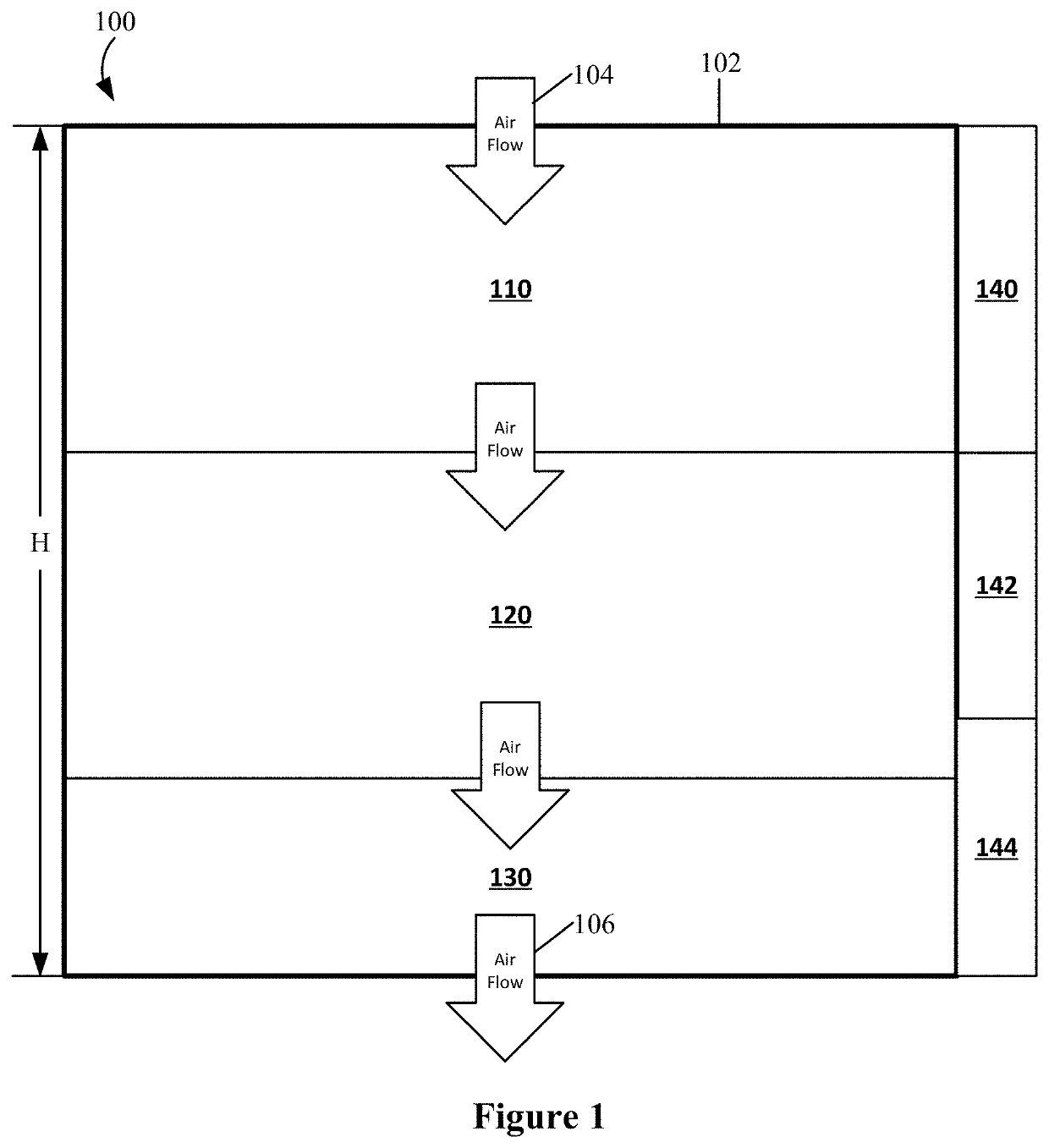
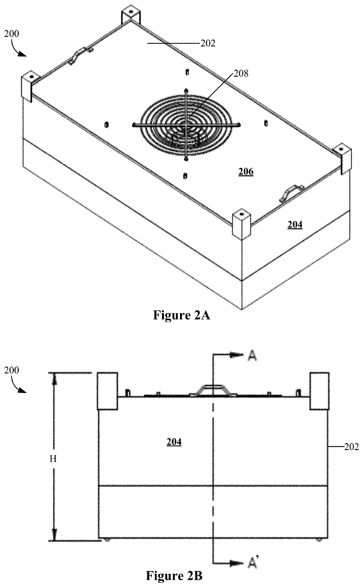
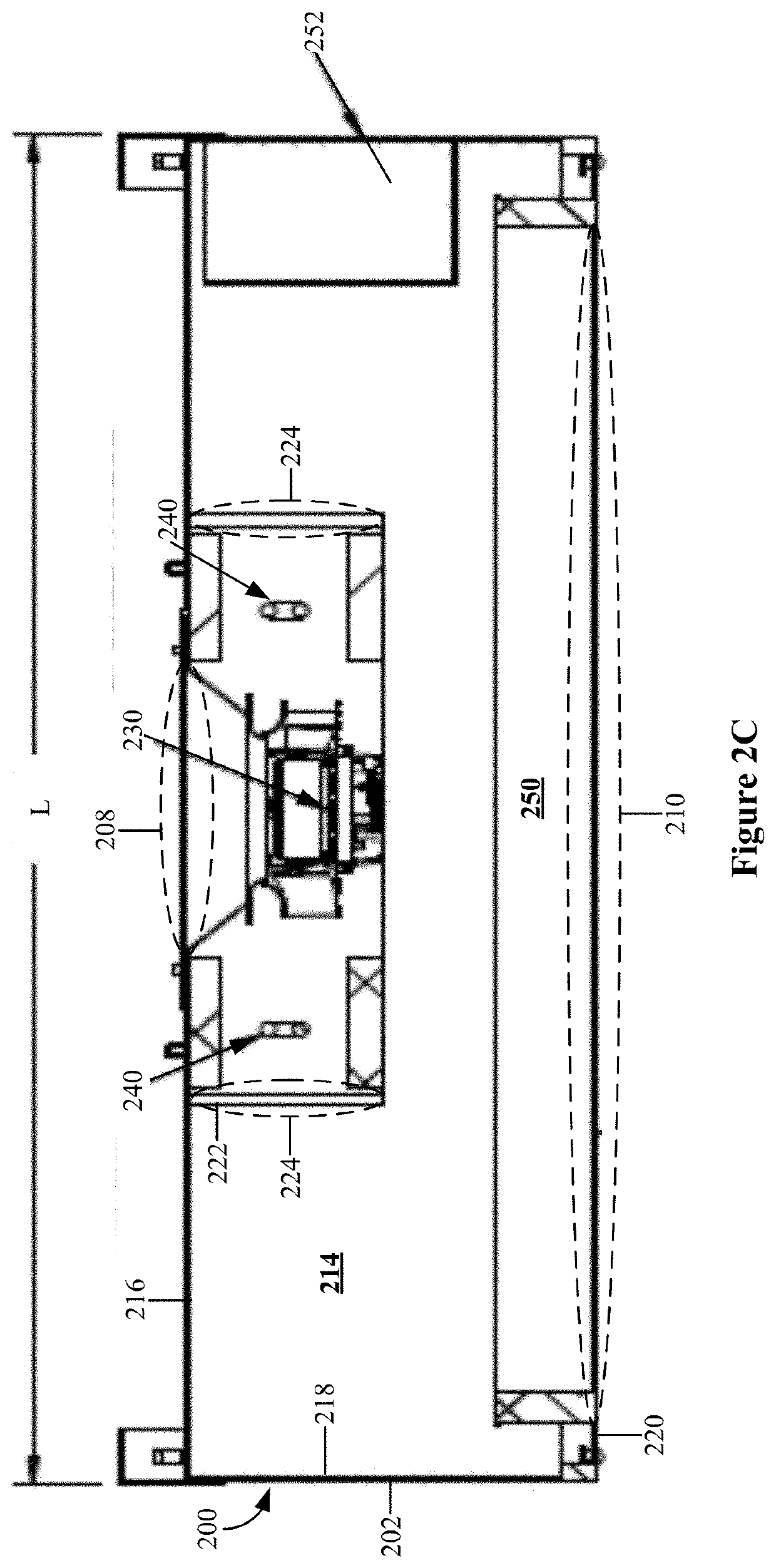
[0015]Fan filter units with an integrated heater are provided. By integrating a heater into a traditional fan filter unit used in mobile and / or modular cleanrooms and / or laboratories, the overall amount of space required for the fan filter unit and the heater is reduced. Indeed, fan filter units with an integrated heater provided herein are designed to be placed within the ceiling, or even a wall, allowing for more space that can be utilized for other functions that would normally be occupied by the fan filter unit and / or the heater unit, which is even more critical in cleanrooms and / or laboratories that have limited space such as mobile and / or modular cleanrooms and / or laboratories. The placement of the heater (e.g., downstream of the blower motor) reduces overheating and / or tripping of the blower motor. The placement of the air filter (e.g., proximal / flush with the ceiling) allows for ceiling-side access to the components within the fan filter unit with the integrated heater, incl...


PUM


Abstract

A fan filter unit with an integrated heater system includes a housing comprising an air intake and an air outlet; a blower motor mounted within the housing and downstream of the air intake; a heater mounted within the housing and downstream of the blower motor; and an air filter mounted within the housing. In some cases, the system further includes an inner housing mounted to a top of an inside portion of the housing, the inner housing having an inner housing air outlet, where both the blower motor is mounted within the inner housing and the heater is mounted within the inner housing. In some of such cases, the air intake and the air outlet are positioned to direct an air flow vertically and the inner housing air outlet is positioned to direct an air flow horizontally.

Description

BACKGROUND[0001]There is a need for additional pharmaceutical cleanroom space, as well as cleanroom (and / or laboratory) infrastructure for a range of bioprocessing and biomanufacturing applications. However, additional space for these cleanrooms (and / or laboratories) may take years to build due to the complexity of the requirements for these facilities. Furthermore, there may not be room anywhere close to existing cleanroom (and / or laboratory) facilities to build new space. Therefore, mobile (e.g., towable) and modular (e.g., prefabricated and designed for permanent and / or semi-permanent placement) cleanrooms have become increasingly popular.[0002]Due to the limits set on the size of mobile and modular cleanroom space (e.g., due to limitations in shipping size and other factors), space within mobile and modular laboratories is meticulously planned out and utilized to the fullest extent possible. One critical requirement for mobile and / or modular cleanrooms is that the air brought in...

Claims


Application Information

Patent Timeline
Patent Type & Authority Applications(United States)
IPC IPC(8): F24F7/007F24F13/20F24F13/28
CPCF24F7/007F24F13/20F24F13/28F24F2013/205F24F2221/34F24F2110/10F24F2110/20
Inventor SERLE, JEFFREY Q.MACDUFFIE, PHILLIP JOSEPH
Owner GERMFREE LAB INC
Learn More