
Suction rod assembly for well fluid extraction and related methods

a well fluid extraction and sucker rod technology, applied in the direction of positive displacement liquid engines, well accessories, liquid fuel engines, etc., can solve the problems of inability to recover linear scoring of barrels or plungers, requires replacement, and non-linear abrasions on the plunger surface. , to achieve the effect of reducing the number of plungers

Pending Publication Date: 2022-11-03
SNOW JERRY MARK
View PDF12 Cites 0 Cited by
  • Summary
  • Abstract
  • Description
  • Claims
  • Application Information

AI Technical Summary

Benefits of technology

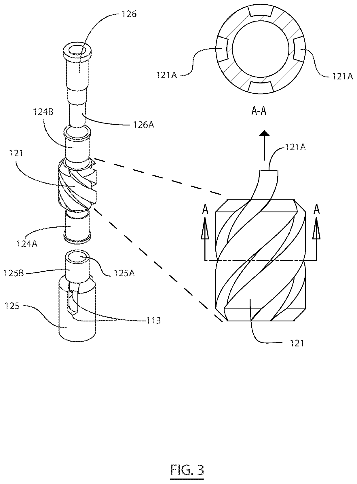
The present invention is a suction rod pump assembly for use in oil and gas drilling operations. The assembly includes a rotor with flutes that rotate around a central axis. The flutes create a horizontal force on the rotor, allowing it to rotate freely. The rotor is not fixedly joined to the plunger, so the rotational force is not transferred to the plunger. The flutes cause the fluid to transition from a laminar flow to a turbulent flow, which prevents heavy debris from settling in the plunger barrel boundary. The rotor is a swivel rotor that joins the cage to a rod lock, allowing it to rotate freely. The swivel rotor has flutes with a constant pitch and a starting angle of 0 degrees and an ending angle of about 360 degrees. The assembly also includes a traveling valve and a standing valve and seating assembly to control fluid flow. The invention aims to provide an improved suction rod pump assembly with a longer cyclic life.

Problems solved by technology

The particles of sand and stone in the formation fluid are non-ideal and lodge in between a plunger and barrel, which causes irrecoverable linear scoring of a barrel or plunger and requires replacement.
However, the rotation of the plunger fails to prevent wear on the plunger; instead, the adapter distributes the wear uniformly around the plunger, producing non-linear abrasions on the plunger surface, yielding helical scoring on either the plunger or the barrel.
Although the vortex may prevent fluid debris from settling, the angular velocities of the vortex are limited because the energy potential of fluids velocity transfers to the entire plunger assembly, and the heavier particles lodge into the boundary.
An assembly or device has yet to provide a simple solution to prevent formation fluid containing particles of sand or rock from penetrating between the barrel and plunger walls without introducing a torque to the system.

Method used


Image

  • Suction rod assembly for well fluid extraction and related methods
  • Suction rod assembly for well fluid extraction and related methods
  • Suction rod assembly for well fluid extraction and related methods

Examples


Embodiment Construction

[0037]Reference will now be made in detail to certain embodiments of the invention, examples of which are illustrated in the accompanying drawings. While the invention will be described in reference to these embodiments, it will be understood that they are not intended to limit the invention. To the contrary, the invention is intended to cover alternatives, modifications, and equivalents that are included within the spirit and scope of the invention. In the following disclosure, specific details are given to provide a thorough understanding of the invention. However, it will be apparent to one skilled in the art that the present invention may be practiced without all of the specific details provided.

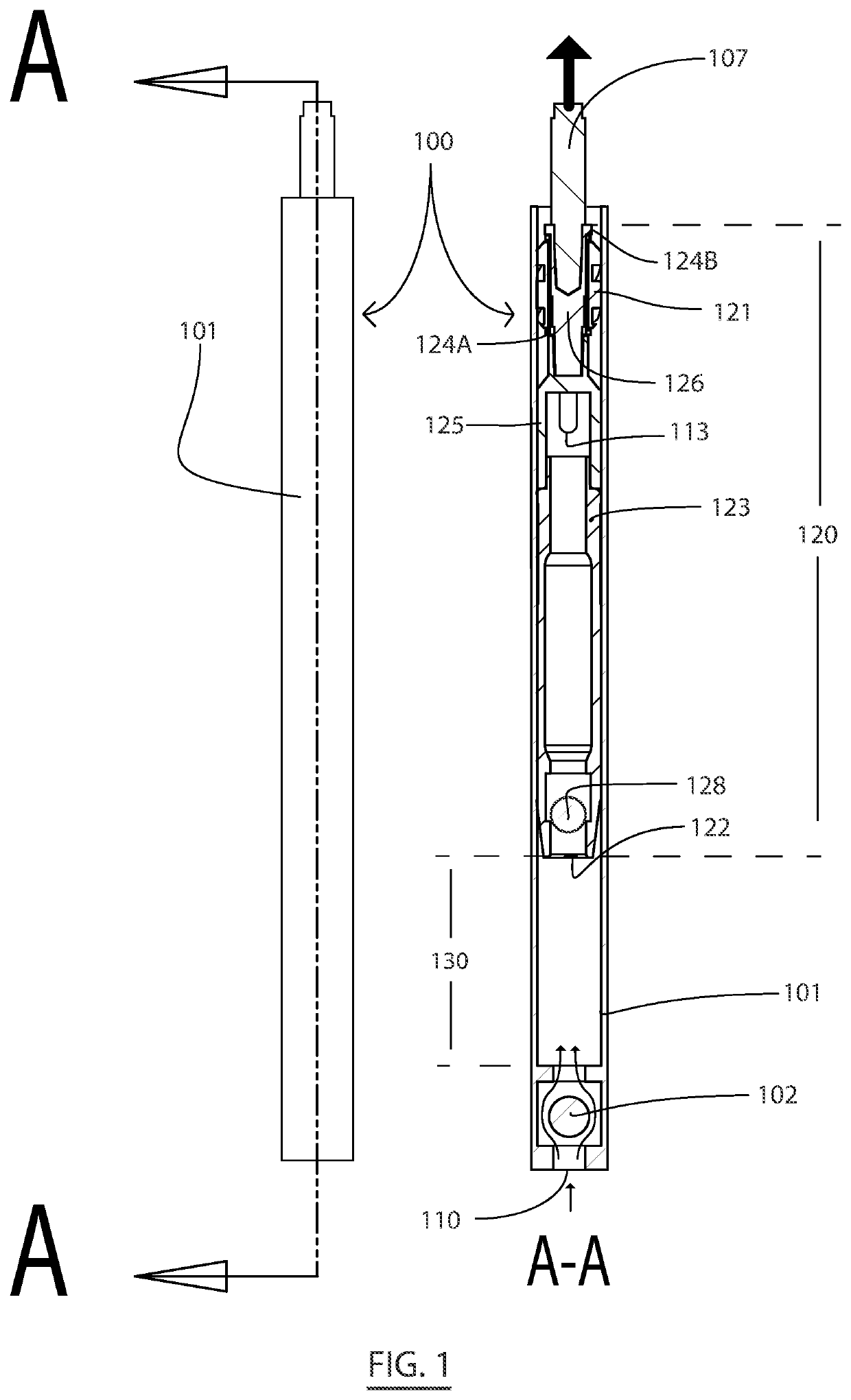
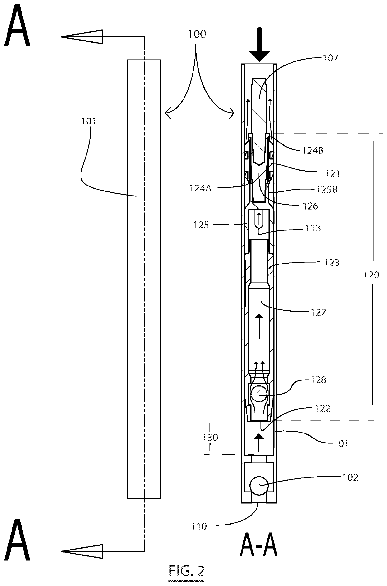
[0038]The present invention concerns a Suction Pump Rod (SPR) system that may be incorporated into a downhole pumping system or other pumping equipment. FIGS. 1-7 provide views of an exemplary SPR assembly 100. FIGS. 1-4 provide views of the SPR assembly 100 incorporating a plunger assem...


PUM


Abstract

The present invention provides a downhole suction rod pump assembly for use in pumping formation fluid from an oil well, and more specifically, provides a rotor operable to generate a vortex in a pump barrel without imparting torque to the plunger. The improvements to a suction rod pump assembly may be incorporated into any oil well pumping system having a linear rod and or rod string. The rotor vortex displaces formation fluid above a plunger assembly, thereby preventing heavier debris in the formation fluid from settling or lodging between a plunger and barrel boundary, thus extending the practical life of the pump.

Description

FIELD OF THE INVENTION[0001]The present invention generally relates sucker rod pumps for use in pumping formation fluid from an oil well, and more specifically, relates to a downhole sucker rod pump assembly with a rotor operable to generate a vortex in a pump barrel without imparting torque to the plunger. The vortex displaces formation fluid above a plunger assembly, thereby preventing heavier debris in the formation fluid from settling or lodging between a plunger and barrel boundary, thus extending the practical life of the pump.BACKGROUND OF THE INVENTION[0002]A downhole sucker rod pump involves the retrieving formation fluid (e.g., thin oil, thick oil-water mixtures containing particles of sand and rock) from wells at depths exceeding 1,000 ft. Some oil wells initially produce formation fluid in the form of a thin oil and as the well becomes depleted, it may produce a thicker oil that, in many cases, contains particles of sand and rock. However, some oil wells produce viscous ...

Claims


Application Information

Patent Timeline
Patent Type & Authority Applications(United States)
IPC IPC(8): F04B23/10F04B23/12F04B47/06
CPCF04B23/10F04B23/12F04B47/06F04B53/00F04B47/026E21B43/126F04B53/14F04B53/12
Inventor SNOW, JERRY MARK
Owner SNOW JERRY MARK
Learn More