Battery Module Comprising Busbar Plate, Battery Pack Comprising Battery Module, and Electronic Device

a battery module and busbar plate technology, applied in the direction of electrical equipment, cell components, vent arrangements, etc., can solve the problems of product using the battery module malfunctioning, fire accidents, malfunctioning, etc., and achieve the effect of reducing the space occupied by the fuse portion, convenient implementation of compact battery modules, and long current paths

Pending Publication Date: 2022-10-27
LG ENERGY SOLUTION LTD
View PDF0 Cites 0 Cited by
  • Summary
  • Abstract
  • Description
  • Claims
  • Application Information

AI Technical Summary

Benefits of technology

The present patent text describes a battery module with a fuse portion that is bent at least once in a horizontal direction, allowing for a longer current path in a compact space. The fuse portion is protected by a protection tube that contracts at a predetermined temperature to prevent heat from externally dissipating when the fuse portion is melted by a high current. This ensures quick disconnection. Additionally, the protection tube reduces the risk of damage to the fuse portion due to continuous vibration. The technical effect of the present patent text is a compact battery module with a bent fuse portion that is easily space-controlled and has increased safety and reliability.

Problems solved by technology

However, a product using the battery module may malfunction when an electric short circuit occurs between some secondary batteries from among the plurality of secondary batteries embedded in the battery module and a high current flows through the busbar through the some secondary batteries.
In this regard, a current may be blocked by using a battery management system (BMS), but there is no countermeasure against the high current when the BMS does not function or malfunctions, thereby leading to a malfunction or a fire accident.

Method used


Image

  • Battery Module Comprising Busbar Plate, Battery Pack Comprising Battery Module, and Electronic Device
  • Battery Module Comprising Busbar Plate, Battery Pack Comprising Battery Module, and Electronic Device
  • Battery Module Comprising Busbar Plate, Battery Pack Comprising Battery Module, and Electronic Device

Examples


Embodiment Construction

[0043]Hereinafter, preferred embodiments of the present disclosure will be described in detail with reference to the accompanying drawings. Prior to the description, it should be understood that the terms used in the specification and the appended claims should not be construed as limited to general and dictionary meanings, but interpreted based on the meanings and concepts corresponding to technical aspects of the present disclosure on the basis of the principle that the inventor is allowed to define terms appropriately for the best explanation.

[0044]Therefore, the description proposed herein is just a preferable example for the purpose of illustrations only, not intended to limit the scope of the disclosure, so it should be understood that other equivalents and modifications could be made thereto without departing from the scope of the disclosure.

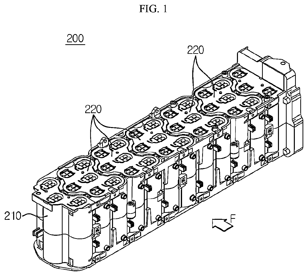
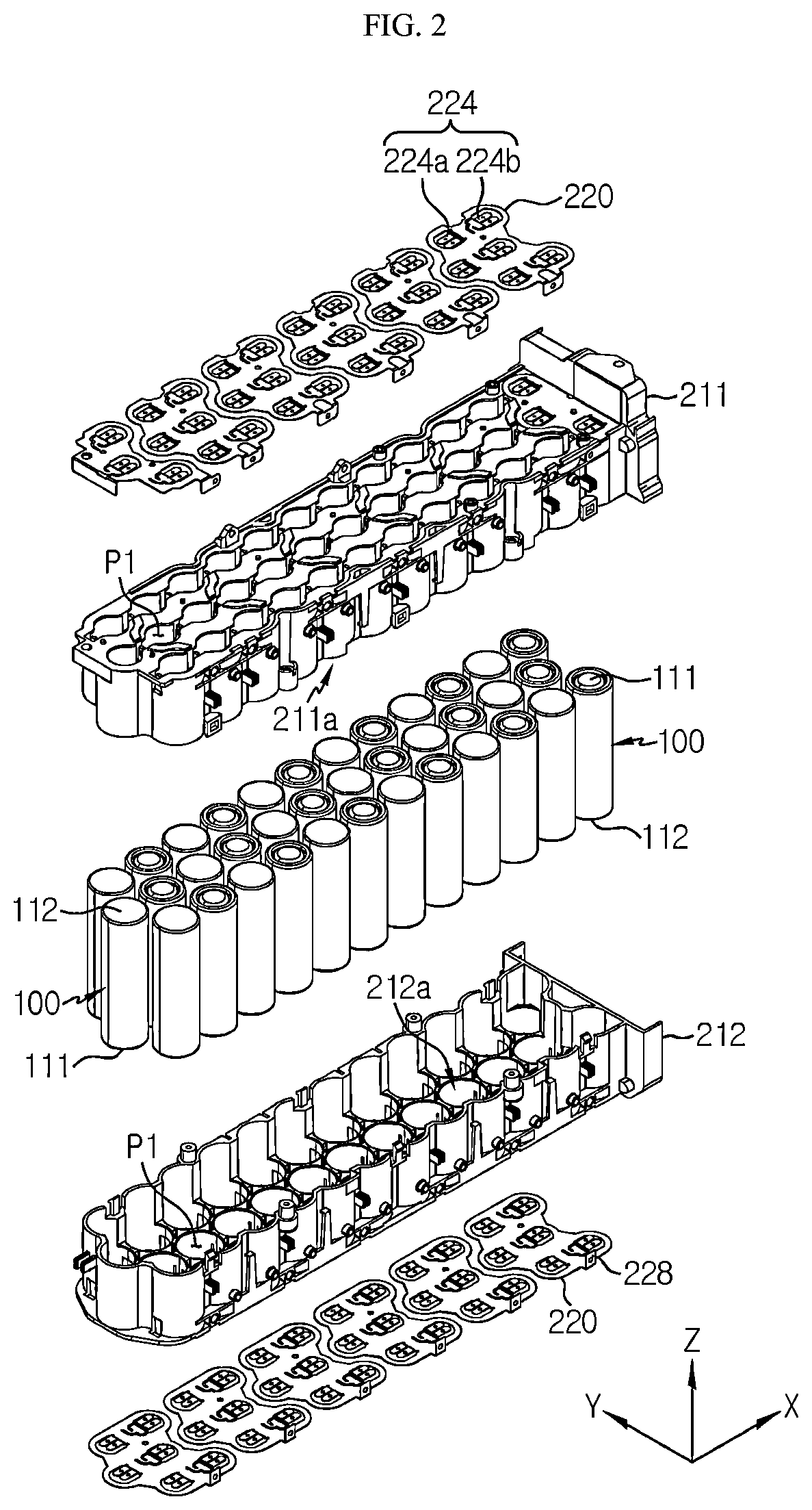
[0045]FIG. 1 is a perspective view schematically showing a battery module according to an embodiment of the present disclosure. FIG. 2 i...


PUM

PropertyMeasurementUnit
currentaaaaaaaaaa
pressureaaaaaaaaaa
currentaaaaaaaaaa

Abstract

A battery module includes: a plurality of cylindrical battery cells including a gas vent portion to discharge an internal gas; and a busbar plate including a plurality of connection terminals that protrude and extend from an inner edge of a connection opening, and to electrically connect the cylindrical battery cells by contacting a positive or negative electrode terminal, and have different shapes depending on the contacted positive or negative electrode terminal, and a connection terminal contacting a positive or negative electrode terminal not having the gas vent portion. The connection terminal includes: a fuse portion to be disconnected when a current of a predetermined level or higher flows from the cylindrical battery cells and having a bent structure bent; and a protection tube to contract at a predetermined temperature with electric insulation and to surround at least a portion of an outer surface of the fuse portion.

Description

TECHNICAL FIELD[0001]The present disclosure relates to a battery module including a busbar plate, a battery pack including the same, and an electronic device, and more particularly, to a battery module including a busbar plate for quickly achieving electrical disconnection when an abnormal behavior (short circuit) of a cylindrical battery cell occurs.[0002]The present application claims priority to Korean Patent Application No. 10-2019-0126474 filed on Oct. 11, 2019, and Korean Patent Application No. 10-2020-0112663 filed on Sep. 3, 2020, in the Republic of Korea, the disclosures of which are incorporated herein by reference.BACKGROUND ART[0003]Recently, with the rapid increase in demands for portable electronic products, such as laptop computers, video cameras, portable phones, and the like, and the regularization of development of electric vehicles, energy storage batteries, robots, satellites, and the like, high-performance secondary batteries capable of being repeatedly charged ...

Claims


Application Information

Patent Timeline
Patent Type & Authority Applications(United States)
IPC IPC(8): H01M50/505H01M50/213H01M50/296H01M50/317H01M50/559H01M50/583
CPCH01M50/505H01M50/213H01M50/296H01M50/317H01M50/559H01M50/583H01M50/507H01M50/502H01M50/548H01M50/30H01M50/595H01M50/581Y02E60/10
Inventor YOON, HYOUNG-CHULLEE, SUK-HOONSON, YOUNG-SU
Owner LG ENERGY SOLUTION LTD
Why Eureka
Try Eureka