
X-ray anti scatter grid

a grid and anti-scatter technology, applied in the field of x-ray anti-scatter grid, can solve the problems of reducing the contrast and contrast-to-noise ratio (cnr) of the image, affecting the anti-scatter performance, and affecting the image quality

Pending Publication Date: 2022-10-27
KONINKLJIJKE PHILIPS NV
View PDF0 Cites 0 Cited by
  • Summary
  • Abstract
  • Description
  • Claims
  • Application Information

AI Technical Summary

Benefits of technology

The patent describes a way to create a 1D ASG structure using existing 1D grid manufacturing technology. This allows for the fabrication of 2D ASGs without significantly modifying the current process. The technique involves using laser drilling and printing technology to create a material that joins the 1D structure into a 2D anti-scatter grid. This results in a cost-effective and flexible method of creating 2D ASGs.

Problems solved by technology

When scattered X-rays from the patient are collected by the imaging detector, they do not provide any additional information about the anatomy of the patients, but they degrade the image quality by reducing the contrast and contrast-to-noise ratio (CNR) of the image.
The use of 1D X-ray anti-scatter grids is well-established in X-ray imaging, but they suffer from too low an anti-scatter performance (too high a scatter-to-primary signal ratio (SPR), and too low a CNR) for next generation (spectral) 3D X-ray Cone-Beam CT (CBCT) and CT imaging systems.
A scattered X-ray photon has a lower (undefined) energy than the original primary X-ray photon, and therefore reduces the spectral energy resolution capability of the X-ray detector if such photons are not absorbed by the anti-scatter grid.
But they suffer from a problem that the thick (≈100 μm) septa walls block the route towards smaller pixel (<1 mm) CT detectors.
Thus, current 2D Direct Metal Laser Sintered (DMLS) tungsten CT ASGs are not compatible with smaller (<1 mm) pixel CT detectors because of the too thick (≈100 μm) septa walls.
Another important disadvantage is the high manufacturing cost.
Other disadvantages again include high manufacturing costs and heavy weight.
This process is critically dependent on maintaining a uniform laser fluence (energy density distribution) to all substrate parts and can lead to contamination of substrate and optical components.
However, as discussed above these 2D structures are very difficult and expensive to fabricate / manufacture.

Method used


Image

  • X-ray anti scatter grid
  • X-ray anti scatter grid
  • X-ray anti scatter grid

Examples


Embodiment Construction

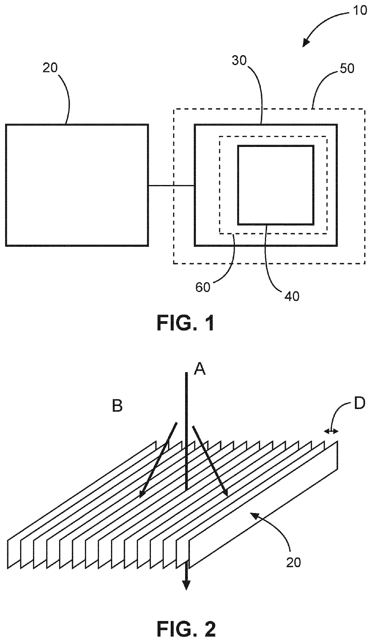
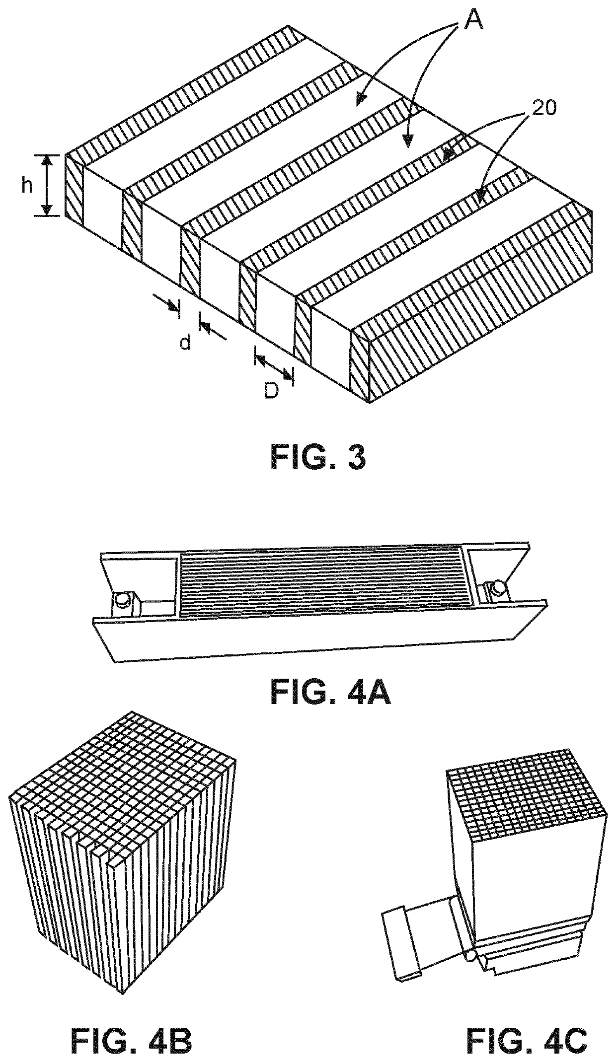
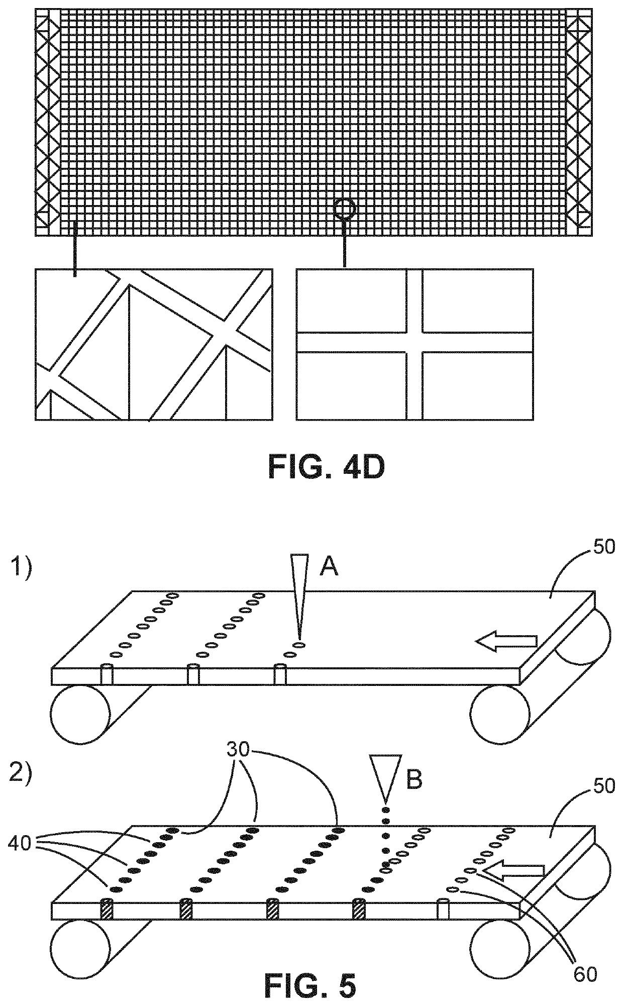
[0047]FIG. 1 shows an example of an X-ray anti-scatter grid 10, where essential features are shown in solid lines and optional features are shown in dashed lines. The X-ray anti-scatter grid is a 2D anti-scatter grid and comprises a plurality of primary septa walls 20, and a plurality of secondary septa walls 30. The plurality of primary septa walls comprise an X-ray absorbing material. The plurality of primary septa walls are substantially parallel to one another. The plurality of secondary septa walls are located between adjacent pairs of walls of the plurality of primary septa walls such that each secondary septa wall is located between an adjacent pair of walls of the plurality of primary septa walls. Each secondary septa wall of the plurality of secondary septa walls is formed from a plurality of columnar structures 40 extending between the plurality of primary septa walls. The plurality of columnar structures comprise an X-ray absorbing material.

[0048]In an example, the primar...


PUM


Abstract

The present invention relates to an X-ray anti-scatter grid (10). The anti-scatter grid comprises a plurality of primary septa walls (20), and a plurality of secondary septa walls (30). The plurality of primary septa walls comprise an X-ray absorbing material. The plurality of primary septa walls are substantially parallel to one another. The plurality of secondary septa walls are located between adjacent pairs of walls of the plurality of primary septa walls such that each secondary septa wall is located between an adjacent pair of walls of the plurality of primary septa walls. Each secondary septa wall of the plurality of secondary septa walls is formed from a plurality of columnar structures (40) extending between the plurality of primary septa walls. The plurality of columnar structures comprise an X-ray absorbing material.

Description

FIELD OF THE INVENTION[0001]The present invention relates to an X-ray anti-scatter grid, a method of manufacturing an X-ray anti-scatter grid, and a method of manufacturing a plurality of secondary septa walls for an X-ray anti-scatter grid.BACKGROUND OF THE INVENTION[0002]When scattered X-rays from the patient are collected by the imaging detector, they do not provide any additional information about the anatomy of the patients, but they degrade the image quality by reducing the contrast and contrast-to-noise ratio (CNR) of the image. Hence anti-scatter grids (ASG) have been in use for a number of decades in medical X-ray imaging (e.g. digital radiography, fluoroscopic imaging, 3D X-ray) and X-ray Computer Tomography (CT) imaging to absorb scattered X-rays, and thereby improve image quality.[0003]The use of 1D X-ray anti-scatter grids is well-established in X-ray imaging, but they suffer from too low an anti-scatter performance (too high a scatter-to-primary signal ratio (SPR), and...

Claims


Application Information

Patent Timeline
IPC IPC(8): A61B6/00G21K1/02
CPCA61B6/4291G21K1/025
Inventor JACOBS, JOHANNES WILHELMUS MARIA
Owner KONINKLJIJKE PHILIPS NV
Learn More