
Process for producing flexible OLED screens and flexible OLED screens

a technology of flexible oled and oled screens, which is applied in the direction of identification means, organic semiconductor devices, semiconductor devices, etc., can solve the problems of too large bezels for aircraft environments, too wide crosses or bands formed by adjacent bezels, and not optimally suitable for aircraft environments

Pending Publication Date: 2022-10-06
AIRBUS OPERATIONS GMBH
View PDF0 Cites 0 Cited by
  • Summary
  • Abstract
  • Description
  • Claims
  • Application Information

AI Technical Summary

Benefits of technology

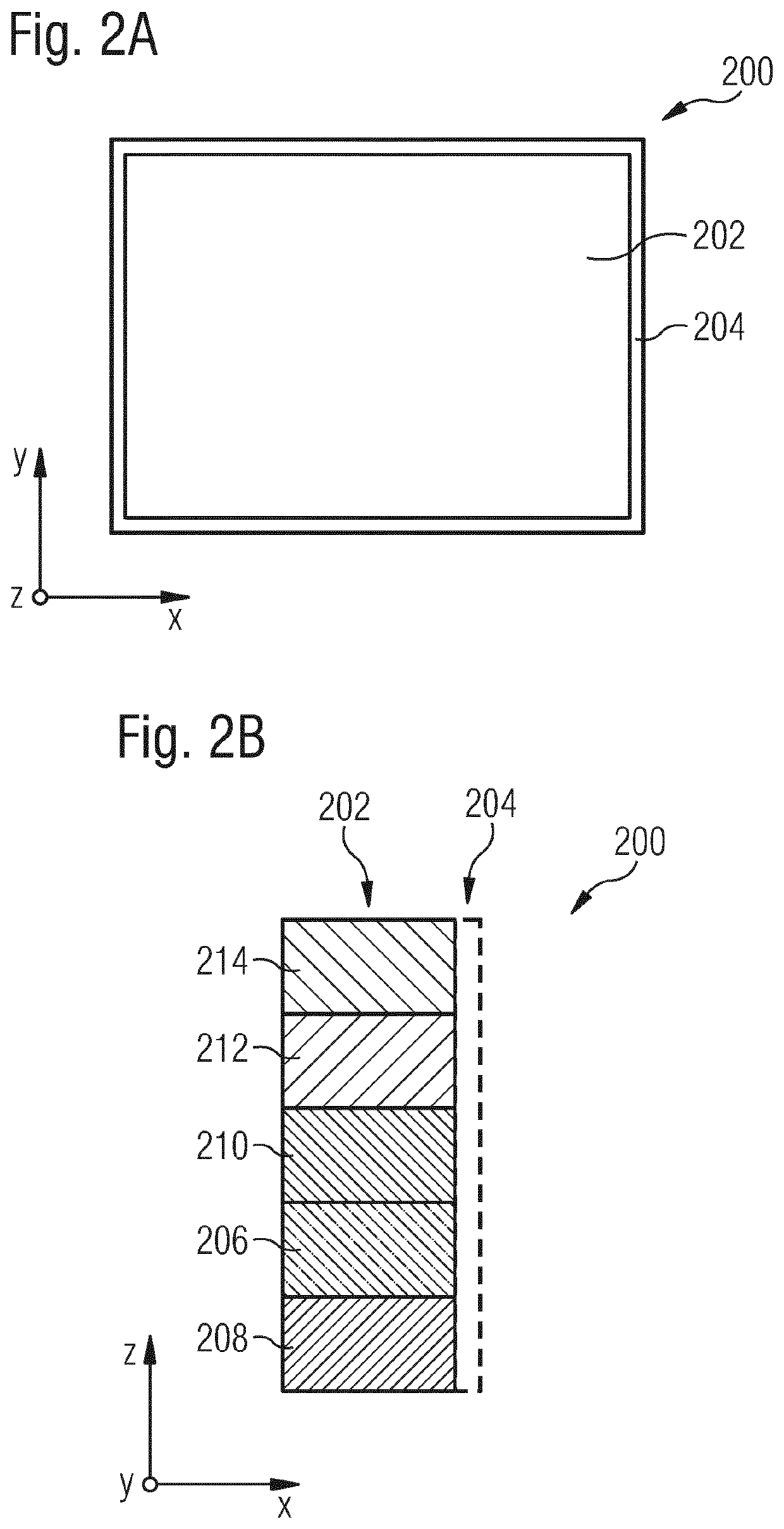
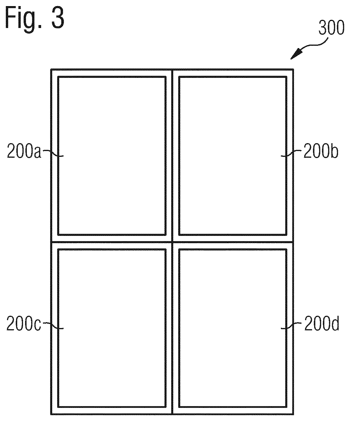
The present invention provides a new way to make OLED screens by eliminating the borders on the screens. The control circuitry is placed behind the thin film transistors layer of the screen, making the screens smaller and more efficient. This allows for the screens to be used in an array without having a large visual impact. Overall, this new process allows for the efficient production of OLED screens for use in places like aircraft.

Problems solved by technology

Accordingly, due to the high costs associated with setting up manufacturing lines for OLED screens, the flexible OLED screens currently being produced are sized for these consumer products and mostly have a rectangular shape.
While these sizes and shapes are acceptable for the various listed consumer goods, it is believed that the sizes and shapes of these screens are not optimally suitable for use in aircraft environments.
For example, while it is known to arrange two or more screens into an array to provide a display surface with an increased surface size compared to just one screen, the current OLED screens have bezels that are too large for use in an aircraft environment when arranged in a multiple panel array.
Thus, the crosses or bands formed by adjacent bezels are too wide when the screens are placed adjacent to one another.
Moreover, even though these OLED screens are being produced for the consumer products, due to the nature of the production processes, it is not a simple task to use existing production lines to produce differently sized screens.
Thus, due to the different sizes and shapes needed and the relatively low production output expected, it is not currently economically feasible to merely set up new production lines to make the OLED screens for an aircraft environment without adjustments to the design of the screens so that they are better able to be utilized in an aircraft environment.

Method used


Image

  • Process for producing flexible OLED screens and flexible OLED screens
  • Process for producing flexible OLED screens and flexible OLED screens
  • Process for producing flexible OLED screens and flexible OLED screens

Examples


Embodiment Construction

[0027]As noted above, the present invention provides OLED screens that are more readily adapted to use in an aircraft environment compared with production OLED screens that are designed for consumer goods. The processes of the present invention provide OLED screens in which the control circuitry is located underneath the OLED and the TFT layers. Thus, the screens produced according to the present processes have reduced, minimized, or eliminated bezels (compared with conventional OLED screens). This facilitates that use of the screens in an array with less area inside the combined display taken up by the adjacent bezels.

[0028]With these above general aspects of the present invention in mind, one or more embodiments of the present invention will be described with the understanding that the following description is not intended to be limiting.

[0029]As shown in FIGS. 1A and 1B, a current OLED display screen 100 includes a display area 102 surrounded by a bezel 104 at the perimeter of th...


PUM


Abstract

Processes for producing an OLED screen with a reduced, minimized, or eliminated bezel section surrounding the display are. The circuitry (206) of the display screen is moved to beneath the OLED (212) and transistor layers (210). The screens with the reduced sized may be installed in an aircraft, and, two or more of the OLED screens with reduced sized may be positioned adjacent to each other so as to form an array.

Description

RELATED APPLICATIONS[0001]This application is a National Stage of International Application No. PCT / EP2020 / 072977 filed on Aug. 17, 2020, which claims priority to U.S. Provisional Patent Application No. 62 / 908,133 filed on Sep. 30, 2019.FIELD OF THE INVENTION[0002]This invention relates generally to flexible organic light emitting diode (“OLED”) screens, to processes for producing such screens, and more particularly to producing such screens for an aircraft and an aircraft having such OLED screens.BACKGROUND OF THE INVENTION[0003]Today's flexible OLED screen market is primarily focused on smartphones, notebooks, monitors, and home displays. Applicant has previously identified the desirability and applicability of incorporating these screens into aircraft. See, International Application No. PCT / EP2019 / 063848, filed on May 28, 2019, and U.S. Prov. Pat. Appl. Ser. No. 62 / 870,839, filed on Jul. 5, 2019, the entireties of which are incorporated herein by reference.[0004]Specifically, it ...

Claims


Application Information

Patent Timeline
IPC IPC(8): H01L51/56H01L51/52H01L27/32
CPCH01L51/56H01L51/5253H01L27/3293H01L2251/566H01L2251/5338G09F9/33H10K59/122H10K71/00H10K59/873H10K59/121H10K59/18H10K59/131H10K2102/311H10K50/844H10K71/851
Inventor MORALES ANTON, ALEJANDRO
Owner AIRBUS OPERATIONS GMBH
Learn More