
Clamp assembly with a heat protection device

Pending Publication Date: 2022-10-06
NORMA GERMANY GMBH
View PDF0 Cites 3 Cited by
  • Summary
  • Abstract
  • Description
  • Claims
  • Application Information

AI Technical Summary

Benefits of technology

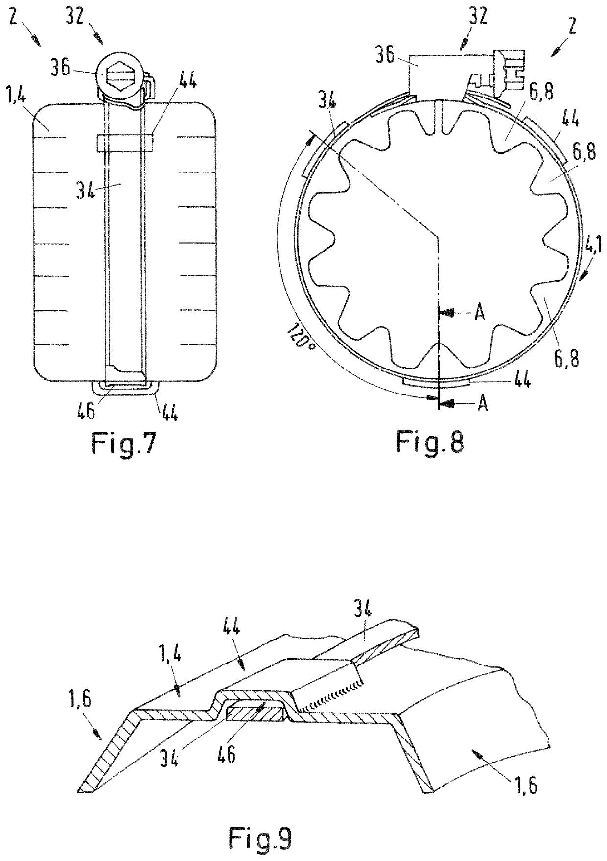
The technical effects of this patent are a clamp assembly with a heat protection device that is easier to assemble and ensures continuous heat protection without interruption. The overlapping portion of the housing is either integrated with it or can be added separately to secure the clamping band. This design makes the assembly process simpler and more efficient, while still providing effective heat protection.

Problems solved by technology

As a result of an uncontrolled heat loss, the efficiency of systems can be impaired.
Furthermore, as a result of a high fluid temperature, a clamp can also become powerfully heated and consequently represent a potential danger for adjacent components which are not heat-resistant.
The arrangement of a heat protection on clamps may be problematic as a result of the varying shape.

Method used


Image

  • Clamp assembly with a heat protection device
  • Clamp assembly with a heat protection device
  • Clamp assembly with a heat protection device

Examples


Embodiment Construction

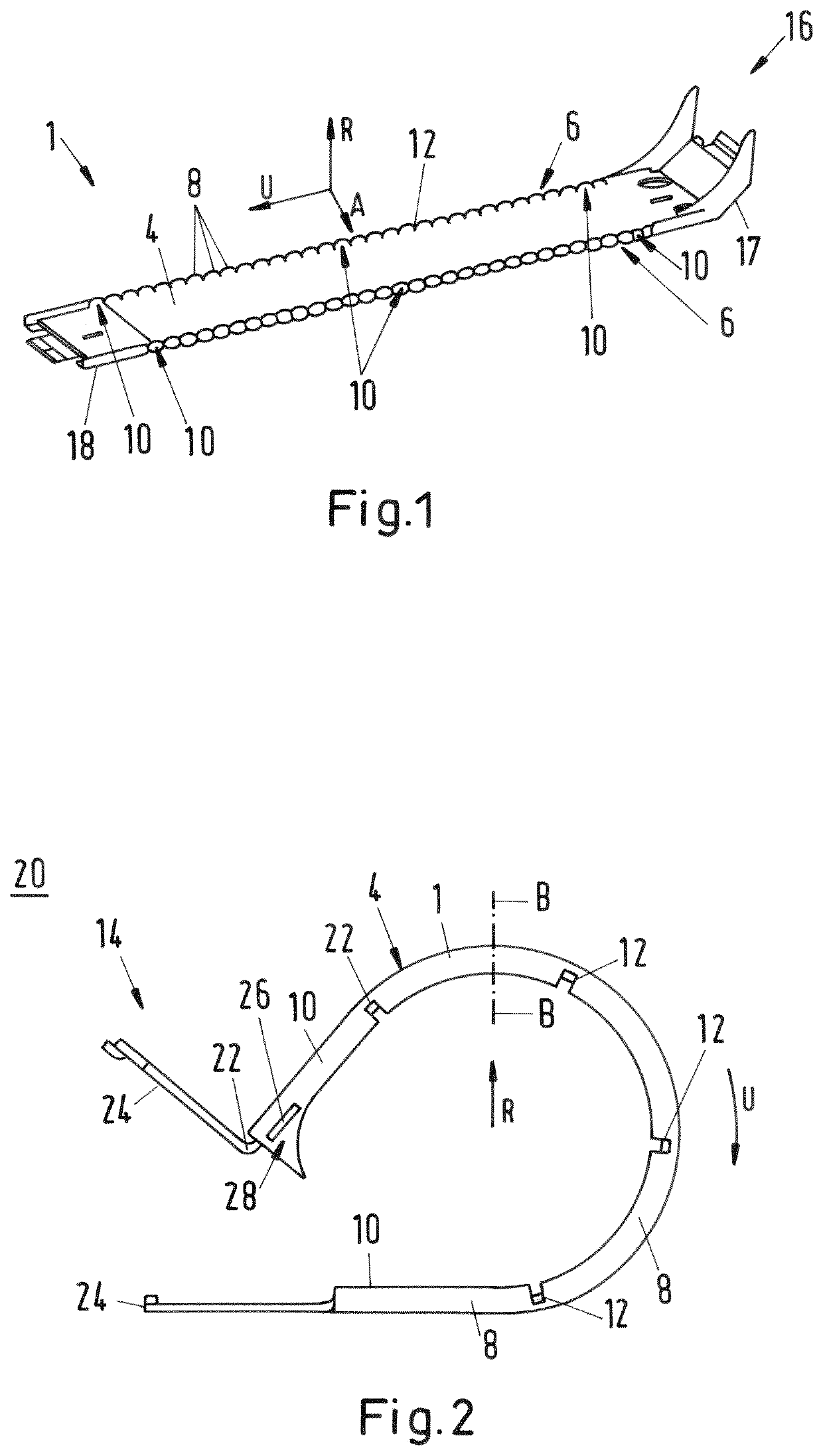
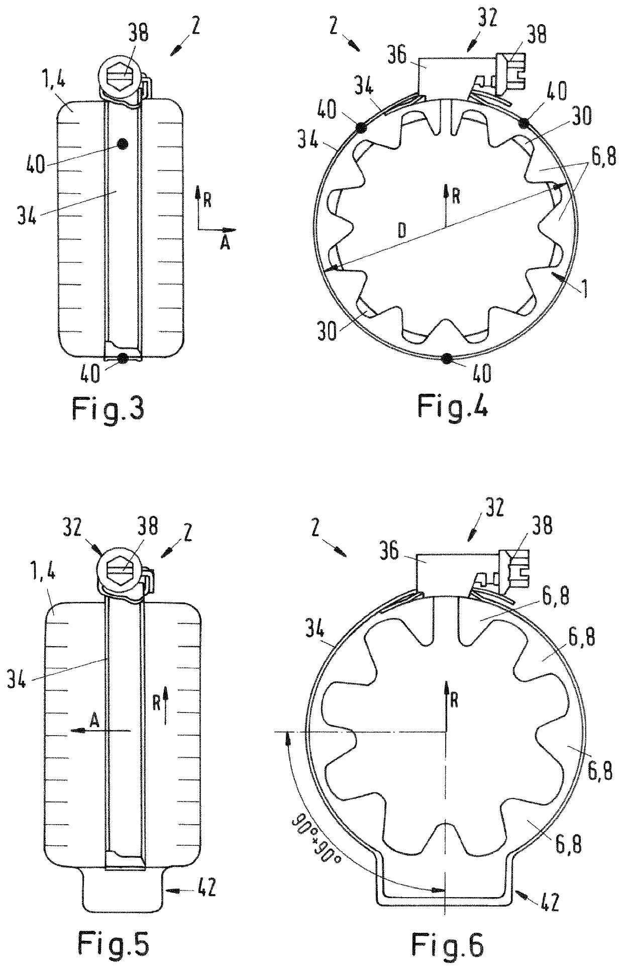
[0050]FIG. 1 is a perspective illustration of a housing 1 of a heat protection device 2 according to an embodiment. The housing 1 has a circumferential wall 4 which extends in a circumferential direction U. At both sides of the circumferential wall 4, a wall or side wall 6 of the housing 1 is configured as an extension of the circumferential wall 4 in an axial direction A. The walls 6 are bent over with respect to the circumferential wall 4 in a radial direction R and form according to the embodiment a right angle with respect to the circumferential wall 4.

[0051]The walls 6 of the housing 1 are subdivided into portions 8, 10 which may be spaced apart from each other by means of recesses 12. The recesses 12 or the portions 8, 10 are formed in this instance in such a manner that the housing 1 can be positioned at the circumference around a clamp 14. In particular, the portions 8, 10 may have a tapered form as the spacing from the circumferential wall 4 increases, whereby the housing 1...


PUM


Abstract

A clamp assembly has a clamp with a clamp band and a clamping device for clamping the clamping band and has a heat protection device with a housing and at least one insulating layer. The housing has a respective wall at each axial end face, the wall being divided into sections and protruding radially inwards, and the at least one insulating layer can be positioned between the walls of the housing. The clamp can be surrounded at least in some regions by the housing and / or the at least one insulating layer of the heat protection device, and the heat protection device is designed to be connectable to the clamp.

Description

INTRODUCTION[0001]The disclosure relates to a clamp assembly having a clamp having a clamping band and having a clamping device for clamping the clamping band, and having a heat protection device having a housing and having at least one insulation insert. Furthermore, the disclosure relates to a heat protection device for a clamp assembly.[0002]In different technical fields, clamps are used to connect hoses or pipes. In particular, clamps can be used to lock hoses or pipes to corresponding supports and consequently to prevent a discharge of a fluid. Such a fluid may, for example, be a heating fluid or a coolant.[0003]Particularly using metal clamps and connectors, a high quantity of heat of the fluid can be discharged to an environment or adjacent components. As a result of an uncontrolled heat loss, the efficiency of systems can be impaired.[0004]Furthermore, as a result of a high fluid temperature, a clamp can also become powerfully heated and consequently represent a potential da...

Claims


Application Information

Patent Timeline
IPC IPC(8): F16L59/18F16L33/08F16L3/123
CPCF16L59/187F16L33/08F16L3/1233F16L3/12F16L3/137F16L33/04F16L59/06
Inventor KRÄMER, MARKUSGEPPERT, HELMUTLANTSMANN, NATAN
Owner NORMA GERMANY GMBH
Learn More