
Transformer unit for a resonant converter

a transformer unit and resonant converter technology, applied in the direction of electric variable regulation, process and machine control, instruments, etc., can solve the problems of more space and more expensive, and achieve the effects of improving thermal properties of switching power supplies, facilitating assembly, and stabilizing shielding elements

Inactive Publication Date: 2019-08-01
FRIWO GERAETEBAU GMBH
View PDF8 Cites 0 Cited by
  • Summary
  • Abstract
  • Description
  • Claims
  • Application Information

AI Technical Summary

Benefits of technology

The invention aims to optimize a transformer unit for a resonant converter, reduce assembling complexity, and lower costs while achieving a compact and stable design. Specifically, the invention aims to reduce the number of electrical and mechanical components needed for the converter, as well as decrease the size of the transformer. The technical effects of the invention include simplifying the design and reducing the size of the transformer unit for resonant converters.

Problems solved by technology

Furthermore, an integrated transformer is particularly advantageous as a nearly ideal transformer with a separate inductor would need more space and is also more expensive.

Method used


Image

  • Transformer unit for a resonant converter
  • Transformer unit for a resonant converter
  • Transformer unit for a resonant converter

Examples


Embodiment Construction

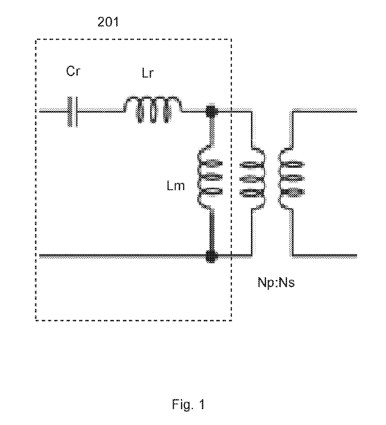
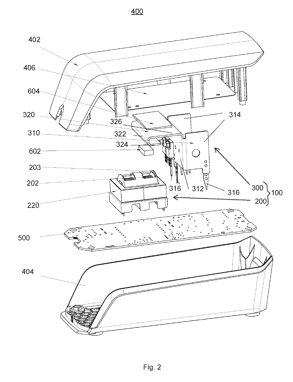
[0042]The present invention will now be explained in more detail with reference to the Figures and firstly referring to FIG. 2. FIG. 2 shows an exploded view of a switching power supply 400. The switching power supply 400 comprises a housing formed by a cover element 402 and a bottom element 404. The housing elements are made of an isolating material such as a plastic. The housing elements serve to mechanically support and protect the integrated parts. In particular, the cover element 402 comprises a heat sink element 406, also referred to as second heat sink 406, and the bottom element 404 supports a printed circuit board (PCB) 500. The PCB serves for mechanically supporting and electrically contacting the transformer unit 100.

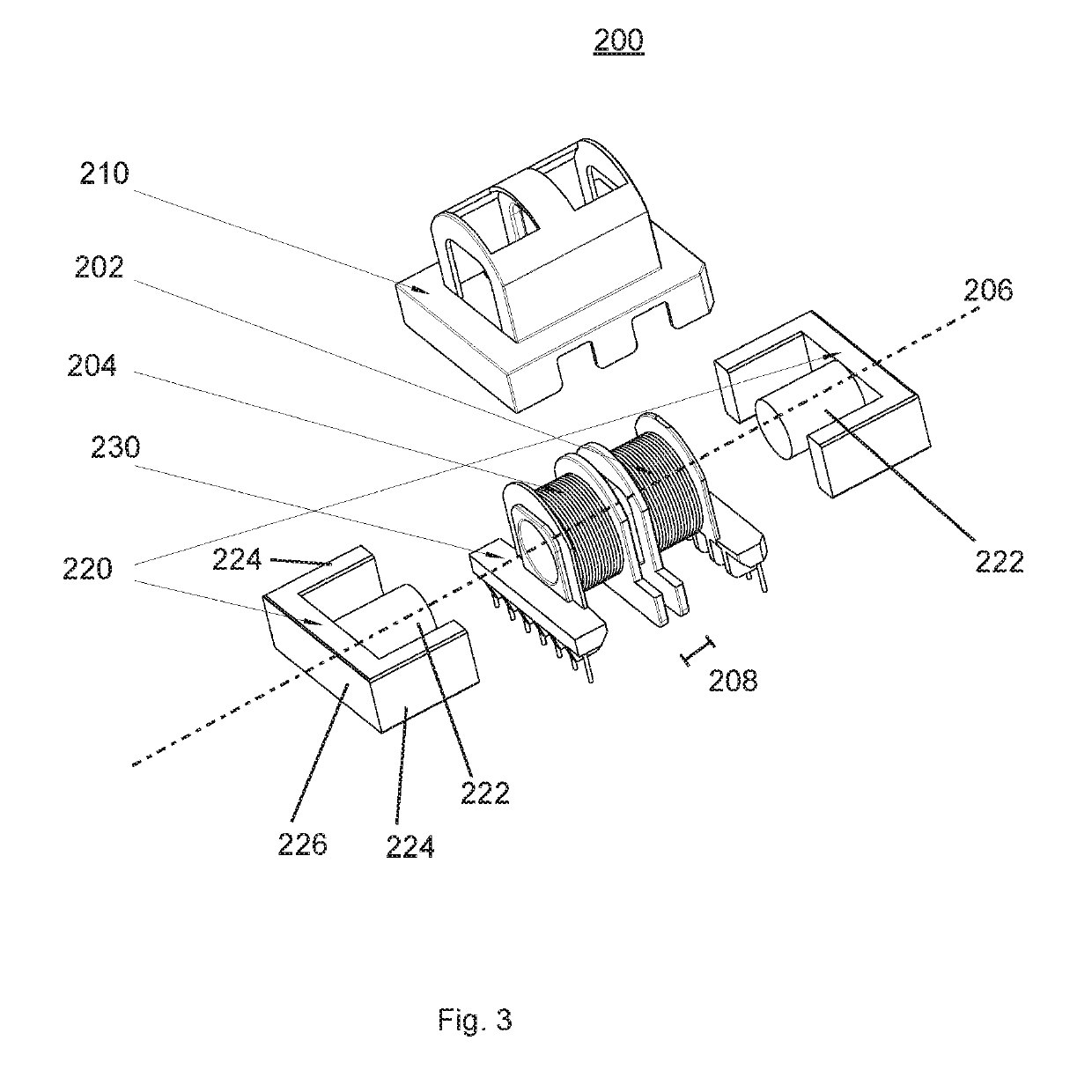
[0043]The transformer unit 100 comprises a transformer 200 and a shielding element 300. The transformer 200 is described in detail with reference to FIG. 3. The transformer 200 comprises a primary winding 202 and a secondary winding 204. In particular, the tr...


PUM


Abstract

A transformer unit for a resonant converter comprising; a primary winding loosely coupled by induction to at least one secondary winding, whereby a leakage inductance is generated, and a shielding element covering at least one of the primary winding or the secondary winding for blocking electromagnetic noise generated by the leakage inductance, wherein the shielding element is thermally coupled to at least one of the primary winding or the secondary winding for transferring heat generated by the transformer unit.

Description

FIELD[0001]The present invention relates to a transformer unit for a resonant converter. Further, the present invention relates to a resonant converter comprising said transformer unit. Additionally, the present invention relates to a switching power supply comprising said resonant converter.[0002]Generally, resonant power conversion has the advantage of smooth waveforms and high power density. Operating a converter in resonant mode, at the point where the impedance between the input and output of the circuit is at its minimum, also provides improved efficiency. From their physical principle, resonant converters are switching converters that include a resonant tank circuit actively participating in determining input-to-output power flow. Resonant converters are based on a resonant inverter, i. e. a system that converts a DC voltage into a sinusoidal voltage (more generally, into a low harmonic content AC voltage), and provides AC power to a load. To do so, a switch network typically...

Claims


Application Information

Patent Timeline
IPC IPC(8): H01F27/28H01F27/32H01F27/36H01F27/24H01F27/08H02M3/335H02M1/44
CPCH01F27/288H01F27/325H01F27/365H01F27/24H01F27/08H02M3/33507H02M1/44H01F27/36H02M3/28H01F27/363H01F27/22H01F27/303H01F27/32H01F38/08
Inventor XU, LINZHONG
Owner FRIWO GERAETEBAU GMBH
Learn More