
A tool for a bending press and an apparatus for monitoring the stress exerted by said tool

a technology of bending press and tool, which is applied in the direction of force measurement, manufacturing tools, instruments, etc., can solve the problems of insufficient parameters to ensure the application of uniform bending force, inconvenient use, and inability to produce aesthetic or functional defects in bent metal sheets

Pending Publication Date: 2022-10-06
ROLLERI
View PDF0 Cites 2 Cited by
  • Summary
  • Abstract
  • Description
  • Claims
  • Application Information

AI Technical Summary

Benefits of technology

The present invention provides a tool that allows monitoring of force values on a metal sheet during set-up and execution of bending cycles. This device is simple to use and practical, and it can detect anomalies quickly. The monitoring system uses optical fibers connected to the sheet.

Problems solved by technology

In fact, these parameters allow determination of a bending force value that is sufficient to complete bending but not sufficient to damage the metal sheet and / or the tooling.
However, in practice for various reasons the force exerted by said tools might not be uniform, i.e. greater is some areas of the metal sheet with respect to others.
When this variability is very marked, it can produce aesthetic or functional defects in the bent metal sheet.
This can occur, for example, when the actuators of the press are not perfectly regulated, or the tools have geometric tolerances that are too high or in the case in which said tools are not accurately mounted.
However, these parameters are not sufficient to ensure the application of a uniform bending force or to detect whether there is an anomaly from this point of view.
In some cases, when said bending force is too high, the metal sheet, but also the tools or even the press itself, can sustain damages.
In fact, in the case in which a thrust value higher than the rated value is set in the monitoring system of the machine, when the punch reaches its end of the stroke bringing the metal sheet into contact with the bottom of the die, the force applied generates pressure that is too high between the surface of the metal sheet and the surface of the tool, with the risk of also damaging the punch and / or the die.
Another problem that occurs with prior art presses and tools is that of not being able to collect, and hence make use of, complete information regarding the actual use of the machine and of the tools.
In particular, it is not currently possible to collect historical data on some working parameters, such as the actual load applied to the tools during each bending cycle or the arrangement of the tools in the press during said machining cycles.
In fact, only very few machines are currently equipped with optical devices, which are costly, delicate and complicated to develop, capable of detecting and recording the position of the section of metal sheet to be bent with respect to the length of the cross beam.
Therefore, in most cases it is not possible to know, in the various bending cycles carried out by a press and by a given tool, whether these have been placed in the correct or ideal position, i.e., more or less at the centre of the cross beam, or in a more critical and less suitable position, i.e. toward one or the ends thereof, thereby causing the press to work in an unbalanced manner.

Method used


Image

  • A tool for a bending press and an apparatus for monitoring the stress exerted by said tool
  • A tool for a bending press and an apparatus for monitoring the stress exerted by said tool
  • A tool for a bending press and an apparatus for monitoring the stress exerted by said tool

Examples


Embodiment Construction

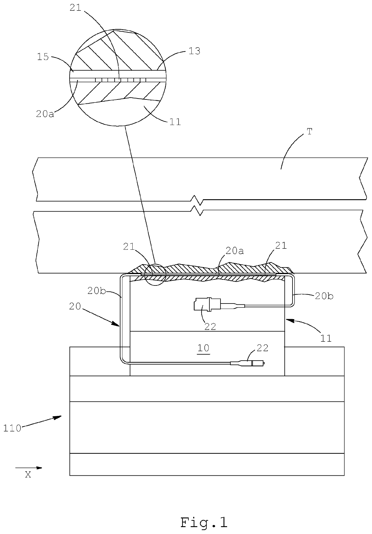
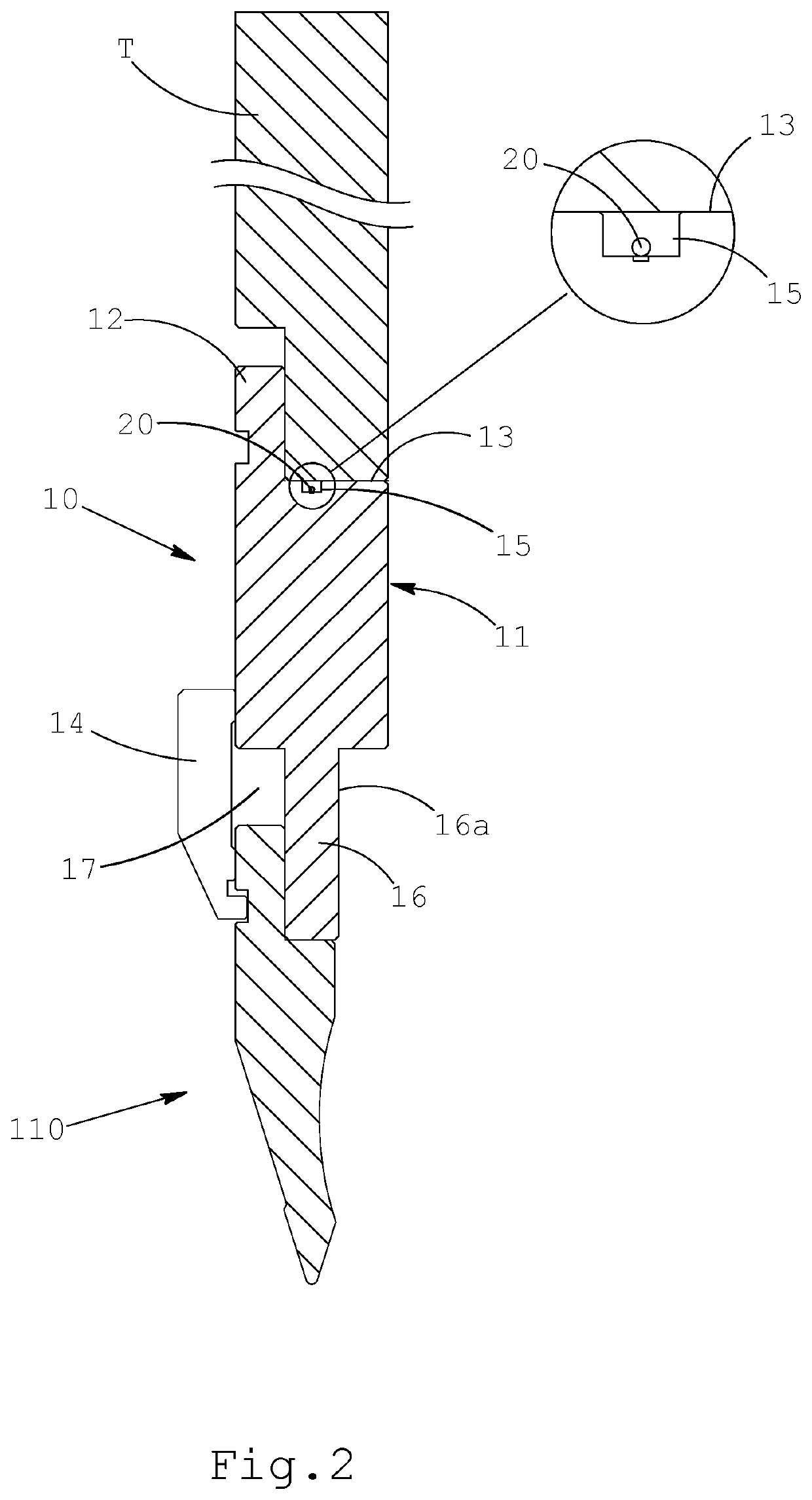
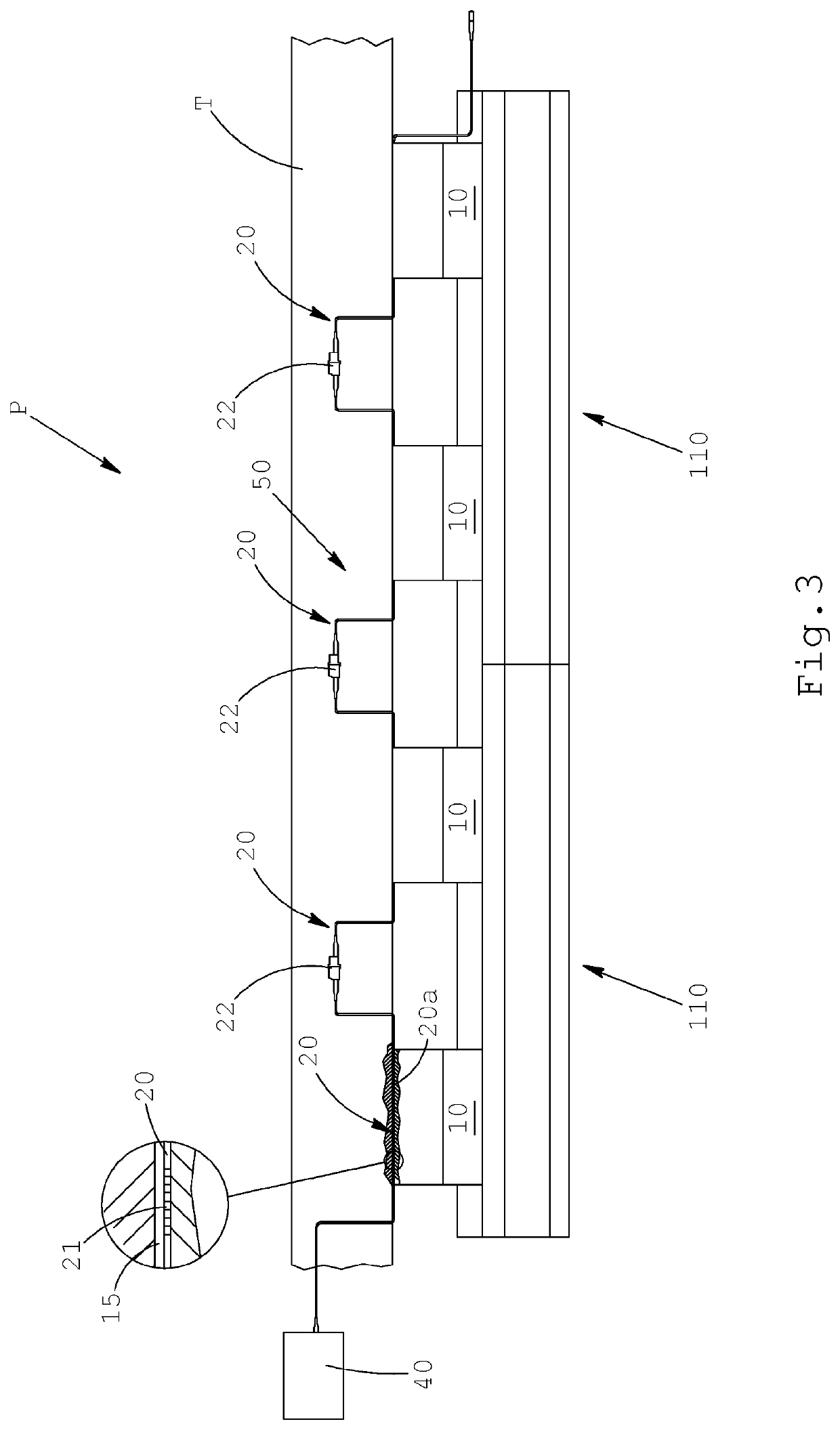
[0082]With reference to the accompanying FIGS. 1 and 2, the number 10 indicates as a whole a tool 10 for a press brake configured as blocking device or “intermediate”, adapted to allow a working tool 110 of punch type to be fixed to the press brake.

[0083]The intermediate 10 comprises a body 11 with a coupling portion 12 in the upper part, generally in the form of shank that extends from an abutment face 13. Said abutment face is generally adapted to abut against a respective surface of the cross beam or “ram” T of the press brake.

[0084]The intermediate 10 further comprises clamping means, typically of shoe type or the like, adapted to clamp a corresponding coupling portion of the punch 110.

[0085]In the example illustrated, said means comprise a shoe 14, or the like, which coacts with a fixed abutment element 16 of the body 11. A seat 17 is produced between said shoe 14 and said fixed abutment element 16, which can house the coupling portion 112 of the punch 110 to be blocked. Typica...


PUM

PropertyMeasurementUnit
widthaaaaaaaaaa
lengthaaaaaaaaaa
sizeaaaaaaaaaa

Abstract

Disclosed is a tool for a press brake, of the type adapted to produce a bend line in a sheet material, where the tool includes a body connectable to a movable or fixed part of a press brake, characterized by including at least one optical fibre a section of which is fixed stably to a surface of the body, and wherein in the section the optical fibre includes at least one Bragg grating.

Description

CROSS-REFERENCE TO RELATED APPLICATIONS[0001]This application is the U.S. national phase of International Application No. PCT / IB2020 / 057477 filed Aug. 7, 2020 which designated the U.S. and claims priority to Italian Patent Application No. 102019000014481 filed Aug. 9, 2019, the entire contents of each of which are hereby incorporated by reference.BACKGROUND OF THE INVENTIONField of the Invention[0002]The present invention concerns a tool for a press brake and a device, which comprises one or more of said tools, configured to monitor the stress (force, thrust) that they exert on a metal sheet during bending. The invention also concerns a press brake equipped with this device.Description of the Related Art[0003]In the machine tool sector, press brakes configured to bend metal sheets, plates or the like by means of cold forming are well known.[0004]Press brakes generally consist of a lower base that defines a fixed abutment on which the metal sheet is placed, which carries a bending di...

Claims


Application Information

Patent Timeline
Patent Type & Authority Applications(United States)
IPC IPC(8): B21D5/02
CPCB21D5/02B21D5/0272B21C51/00G01L1/246
Inventor ARGELLATI, LUCAFERRARIO, MADDALENABRUNERO, MARCO
Owner ROLLERI
Learn More