
Periscopic camera module and electronic device

Pending Publication Date: 2022-09-15
NINGBO SUNNY OPOTECH CO LTD
View PDF0 Cites 3 Cited by
  • Summary
  • Abstract
  • Description
  • Claims
  • Application Information

AI Technical Summary

Benefits of technology

The present patent application aims to provide a solution to reduce the volume occupied by the periscopic camera module. Compared to conventional camera modules, the present application has several technical effects: it can make the periscopic camera module more compact, adapt to larger optical lenses, improve production efficiency and yield, reduce loss caused by light beam passing through different media, improve imaging quality, suppress stray light, reduce the volume of the camera module, improve photosensitive chip light receiving amount, suppress optical path stray light, avoid the risk of introducing stray light, improve imaging quality with different light-shielding structures, improve uniform light receiving amount on different optical surfaces, have anti-shake function, have zoom function, especially high-power zoom capability, and realize anti-shake and zoom functions with a small occupied space.

Problems solved by technology

However, the existing periscopic camera modules have problems such as large size and complex structure.
If the periscopic camera module occupies a large space, the size of other accessories such as batteries and motherboards will be sacrificed, which is not conducive to enhancing the comprehensive value of the mobile phone.
Under the limitation of optical theory, the optical path constructed based on the optical lens with large focal length needs to have sufficient length, which becomes one of the difficulties in reducing the size of the periscopic camera module of mobile phones.
Furthermore, the periscopic module is different from ordinary modules in that its optical path has a turning point, which causes the light to be easily reflected by the structural parts (such as the edge of the lens barrel, the edge of the reflective element, the edge of the bracket, etc.) during the shuttle process, resulting in stray light, which is not conducive to improving the imaging quality.
The telephoto camera module is usually larger than the ordinary camera module, and the number of optical elements is large and complex, which may increase the difficulty of module assembly and the complex assembly process.

Method used


Image

  • Periscopic camera module and electronic device
  • Periscopic camera module and electronic device
  • Periscopic camera module and electronic device

Examples


Embodiment Construction

[0072]For a better understanding of the present application, various aspects of the present application will be described in more detail with reference to the accompanying drawings. It should be understood that these detailed descriptions are merely illustrative of exemplary examples of the present application and are not intended to limit the scope of the present application in any way. Throughout the specification, the same reference numerals refer to the same elements. The expression “and / or” includes any and all combinations of one or more of the associated listed items.

[0073]It should be noted that in this specification, the expressions first, second, etc. are only used to distinguish one feature from another feature and do not imply any limitation on the feature. Accordingly, the first main body discussed below could also be referred to as a second main body without departing from the teachings of the present application.

[0074]In the drawings, the thickness, size and shape of ...


PUM


Abstract

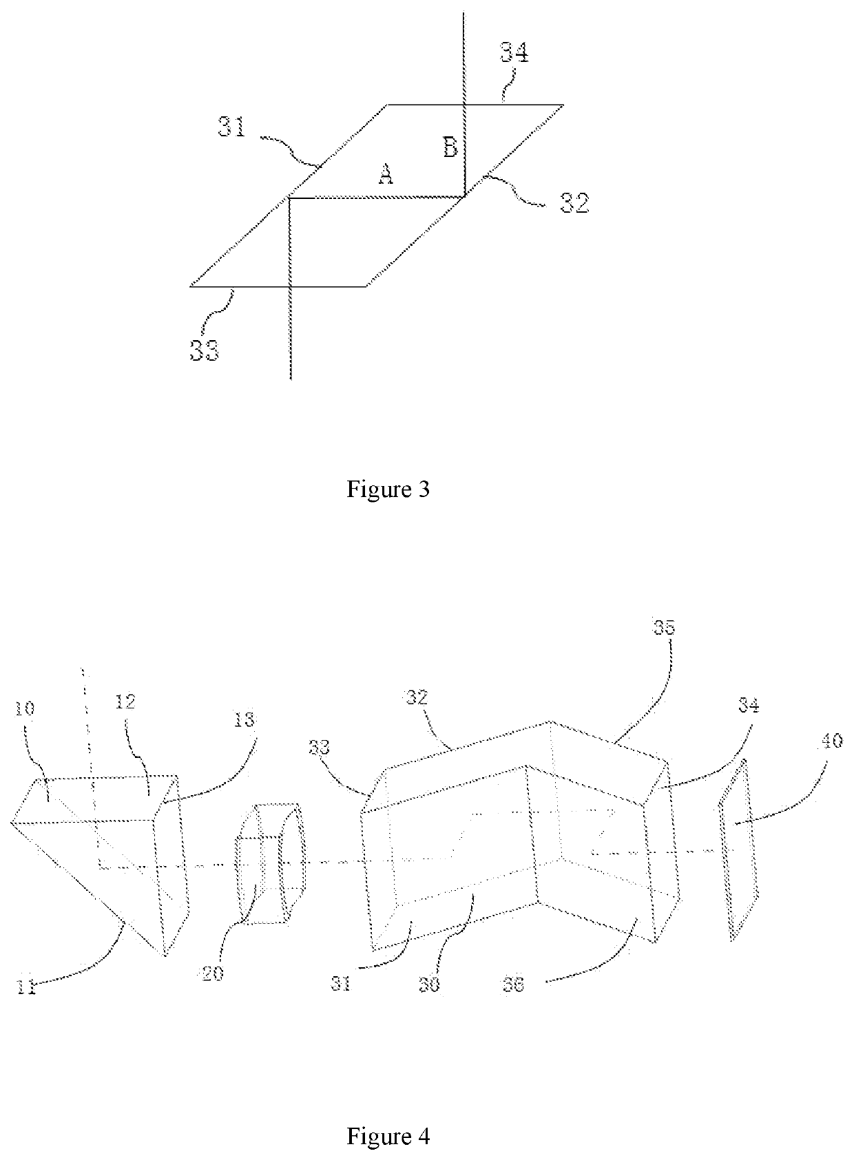
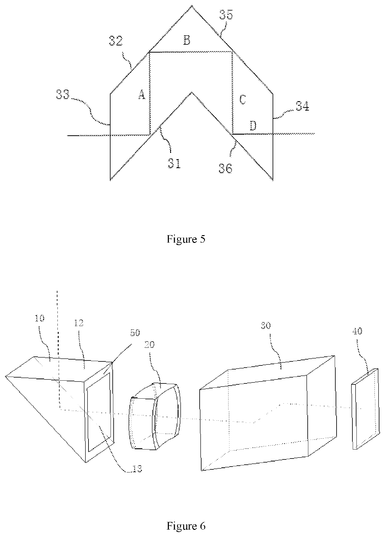
Disclosed is a periscopic camera module, including: a first reflective element including a first reflective surface and used to reflect incident light and make the incident light longitudinally turn; an optical lens used to receive the light reflected by the first reflective element and output an imageable light beam to an image space; a second reflective element including at least one second reflective surface and adapted to make the imageable light beam transversely turn at least once; and a photosensitive chip adapted to receive the transversely turned imageable light beam, wherein at least one of all optical surfaces of the first reflective element and the second reflective element is provided with a light blocking structure, and the light blocking structure is arranged at an edge region of the at least one optical surface; and the optical surface includes a reflective surface, an incident surface, or an eixt surface. According to the present application, the volume of the periscopic camera module can be reduced such that the structure of the periscopic camera module is more compact, and it can be better adapted to an optical lens with a large focal length, and can reduce or avoid the risk of introduction of stray light.

Description

RELATED APPLICATIONS[0001]This application claims three priority rights of the Chinese Patent Application No. 201910879861.4 filed on Sep. 18, 2019, under the title “Periscopic Camera Module and Electronic Equipment”, the Chinese patent application number 201910879844.0 filed on Sep. 18, 2019, under the title “Periscopic Camera Module and Corresponding Electronic Equipment”, and the Chinese patent application number 201910879872.2 filed on Sep. 18, 2019, under the title “Periscopic Camera Module and Electronic Equipment”, and the entire contents of the above three applications are hereby incorporated by reference.FIELD OF THE INVENTION[0002]The present application relates to the technical field of camera module, and in particular, the present application relates to a solution of a periscopic camera module and corresponding electronic device.BACKGROUND OF THE INVENTION[0003]With the popularization of mobile electronic devices, the related technologies of camera modules used in mobile...

Claims


Application Information

Patent Timeline
IPC IPC(8): H04N5/225H04M1/02
CPCH04N5/2254H04M1/0264H04M2250/52G03B17/17G03B30/00G03B2205/0023G03B2205/0069G03B11/045G02B5/20G02B13/0065G02B27/646G02B5/005G02B1/11H04N23/57H04N23/55
Inventor ZHAO, BOJIEYAO, LIFENGYUAN, DONGLIYU, SISIHUANG, ZHEN
Owner NINGBO SUNNY OPOTECH CO LTD
Learn More