
Latch control device

a technology of latch control and control device, which is applied in the direction of non-mechanical control, building locks, construction, etc., can solve the problem that conventional mechanical door locks cannot be used

Active Publication Date: 2022-09-15
I TEK METAL MFG
View PDF10 Cites 0 Cited by
  • Summary
  • Abstract
  • Description
  • Claims
  • Application Information

AI Technical Summary

Benefits of technology

The invention is a latch control device for doors, which has two walls and a detecting module to separate the mounting portion from the hollow portion where components are mounted. This design protects the components from being destroyed, increasing safety. A locking member is designed to prevent fire from spreading by stopping the locking member from pivoting during a fire. The U-shaped stop arms prevent the rotation of the positioning members and are less likely to deform even under high torque. Overall, the invention has improved safety and stability.

Problems solved by technology

As a result, the conventional mechanical door locks cannot be used.

Method used


Image

  • Latch control device
  • Latch control device
  • Latch control device

Examples


Embodiment Construction

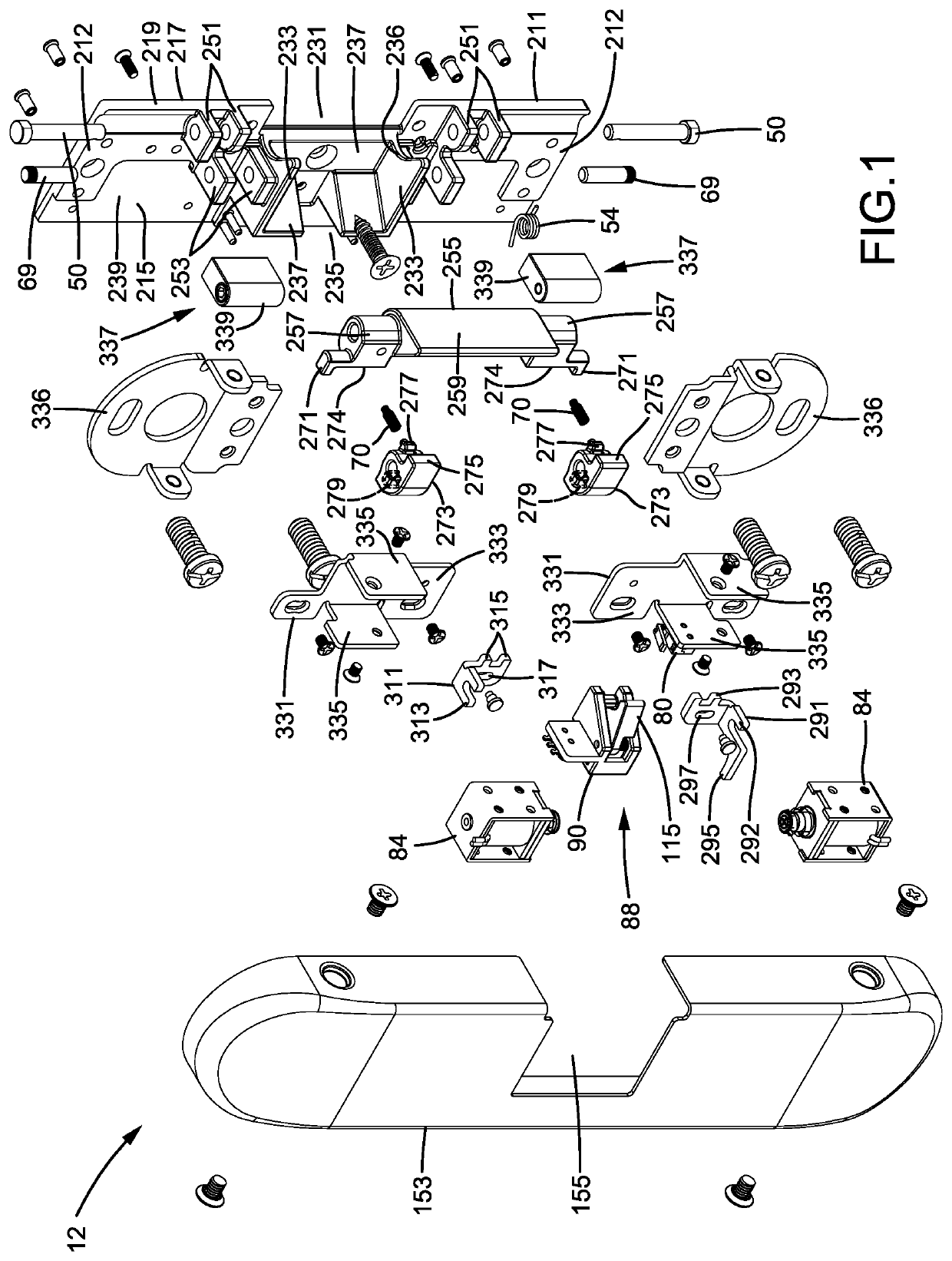
[0041]A latch control device 10 according to the present invention is securely mounted to a door frame 175 to restrain or release a latch 173 of a door lock 171 mounted to a door 176 pivotably mounted to the door frame (FIG. 5). With reference to FIG. 1, the latch control device 12 includes a connecting seat 211 having a first surface 215 and a second surface 217 opposite to the first surface 215. The connecting seat 211 further includes an outer side 219 extending between the first surface 215 and the second surface 217. The connecting seat 211 further includes two walls 233 integrally extending perpendicularly from the first surface 215 along a first axis. The two walls 233 are spaced from each other along a second axis perpendicular to the first axis. A first notch 235 and a second notch 236 are formed between the two walls 233 and are spaced from each other along a third axis perpendicular to the first and second axes. Each of the two walls 233 has substantially L-shaped cross s...


PUM


Abstract

A latch control device includes a connecting seat divided by two integrally formed walls into a hollow portion and a mounting portion spaced from the hollow portion. A detecting module is disposed between the two walls. A locking member is pivotably mounted between the two walls. A first restraining member is disposed in the mounting area and is configured to lock or unlock the locking member, controlling pivotal movement of the locking member. When the locking member is not pivotable, a latch of a door lock in the hollow portion is restrained in the hollow portion, preventing opening of a door to which the door lock is mounted. When the locking member is pivotable, the locking member can pivot while the door pivots, permitting opening of the door.

Description

BACKGROUND OF THE INVENTION[0001]The present invention relates to a latch control device and, more particularly, to an latch control device that can be directly applied to a current mechanical lock to provide electric control of a latch of the mechanical lock.[0002]A door lock is mounted to a door to pivot together with the door relative to a door frame. The door frame includes a fixed latch hole which receives a latch of the door lock when the door is closed, such that the door cannot be opened before retracting the latch out of the latch hole. Furthermore, when the door lock is in a locking state, a key is required to unlock the door lock for subsequently retracting the latch.[0003]With the progress of technology, more and more electric door locks are applied to doors. An electric door lock can cooperate with a door access card, a mobile phone, or other electronic devices to proceed with locking or unlocking operation. However, replacement of an entire mechanical door lock already...

Claims


Application Information

Patent Timeline
Patent Type & Authority Applications(United States)
IPC IPC(8): E05B63/00E05B47/00
CPCE05B63/0069E05B47/0001E05B2047/0086E05B2047/0067E05B47/0047E05B47/0002E05B65/104
Inventor HSU, WEI-CHUNG
Owner I TEK METAL MFG
Learn More