
Image forming apparatus

Pending Publication Date: 2022-08-25
CANON KK
View PDF2 Cites 0 Cited by
  • Summary
  • Abstract
  • Description
  • Claims
  • Application Information

AI Technical Summary

Benefits of technology

The patent text describes an image forming apparatus that can keep hold of paper dust and reduce image defects caused by it.

Problems solved by technology

As the cleanerless methods do not use a cleaning unit that is typically disposed with respect to the drum, paper dust on the drum can cause image defects during a transfer step to the recording material.
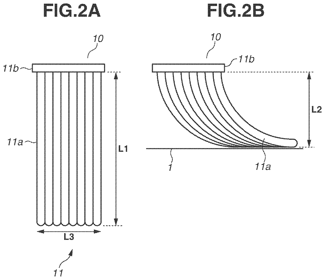
However, with the configuration where the brush is in contact with the drum, paper dust collected and held in the brush can fall on the surface of the drum due to changes in speed in starting and stopping the rotational driving of the drum and partly go through the brush downstream, which can lead to image defects.

Method used


Image

  • Image forming apparatus
  • Image forming apparatus
  • Image forming apparatus

Examples


Embodiment Construction

[0022]Some modes for carrying out the present disclosure will be exemplarily described in detail below based on exemplary embodiments with reference to the drawings. Dimensions, materials, shapes, and relative arrangements of components described in the exemplary embodiments are subject to appropriate changes depending on the configuration and the conditions of an apparatus to which the disclosure is applied. That is, the following exemplary embodiments are not intended to limit the scope of the present disclosure.

1. Image Forming Apparatus

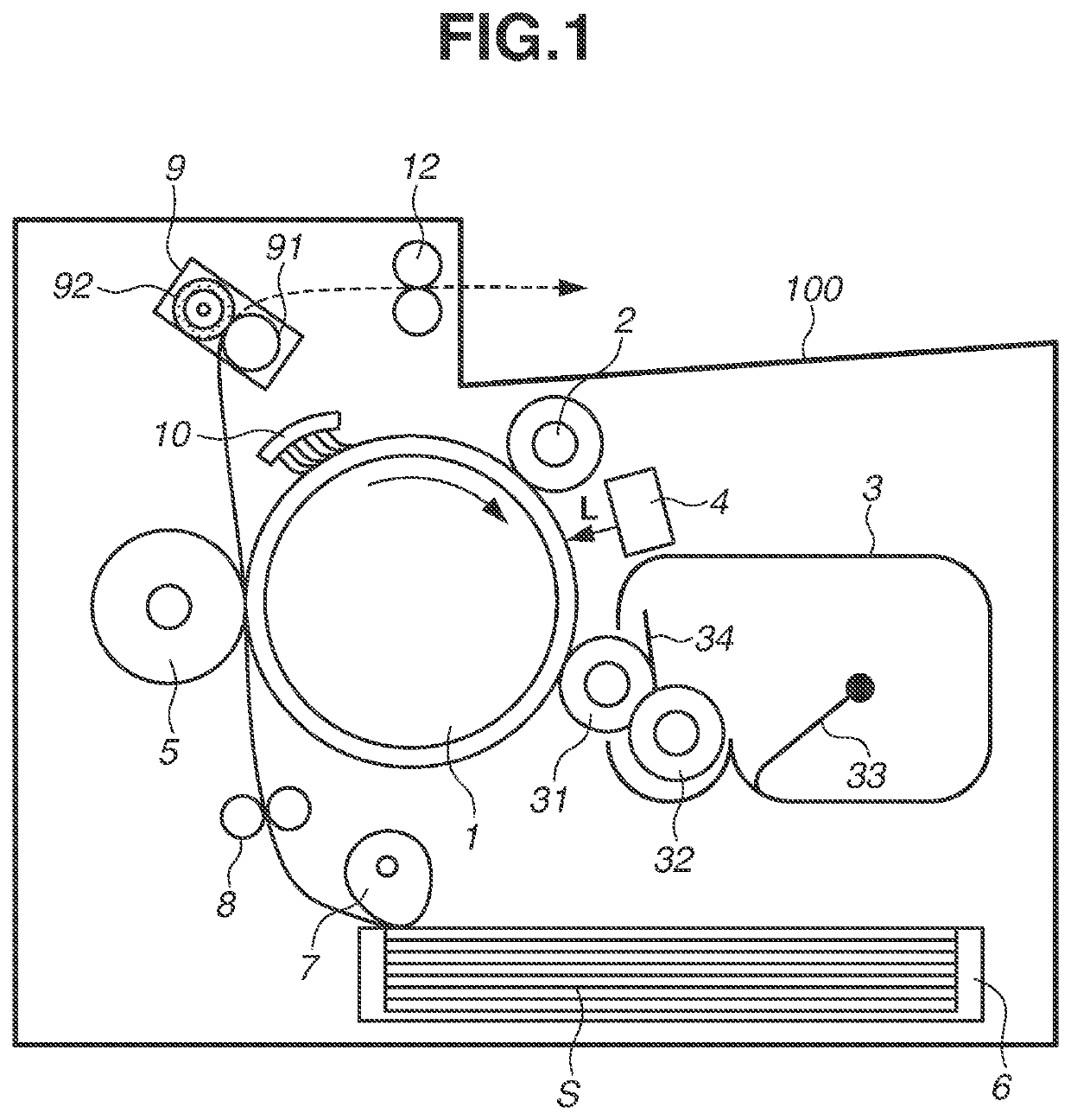
[0023]FIG. 1 illustrates a schematic configuration of an image forming apparatus 100 according to a first exemplary embodiment of the present disclosure.

[0024]The image forming apparatus 100 according to the first exemplary embodiment is a monochrome laser beam printer using a cleanerless contact charging method.

[0025]The image forming apparatus 100 according to the first exemplary embodiment includes a cylindrical photosensitive member serving as...


PUM


Abstract

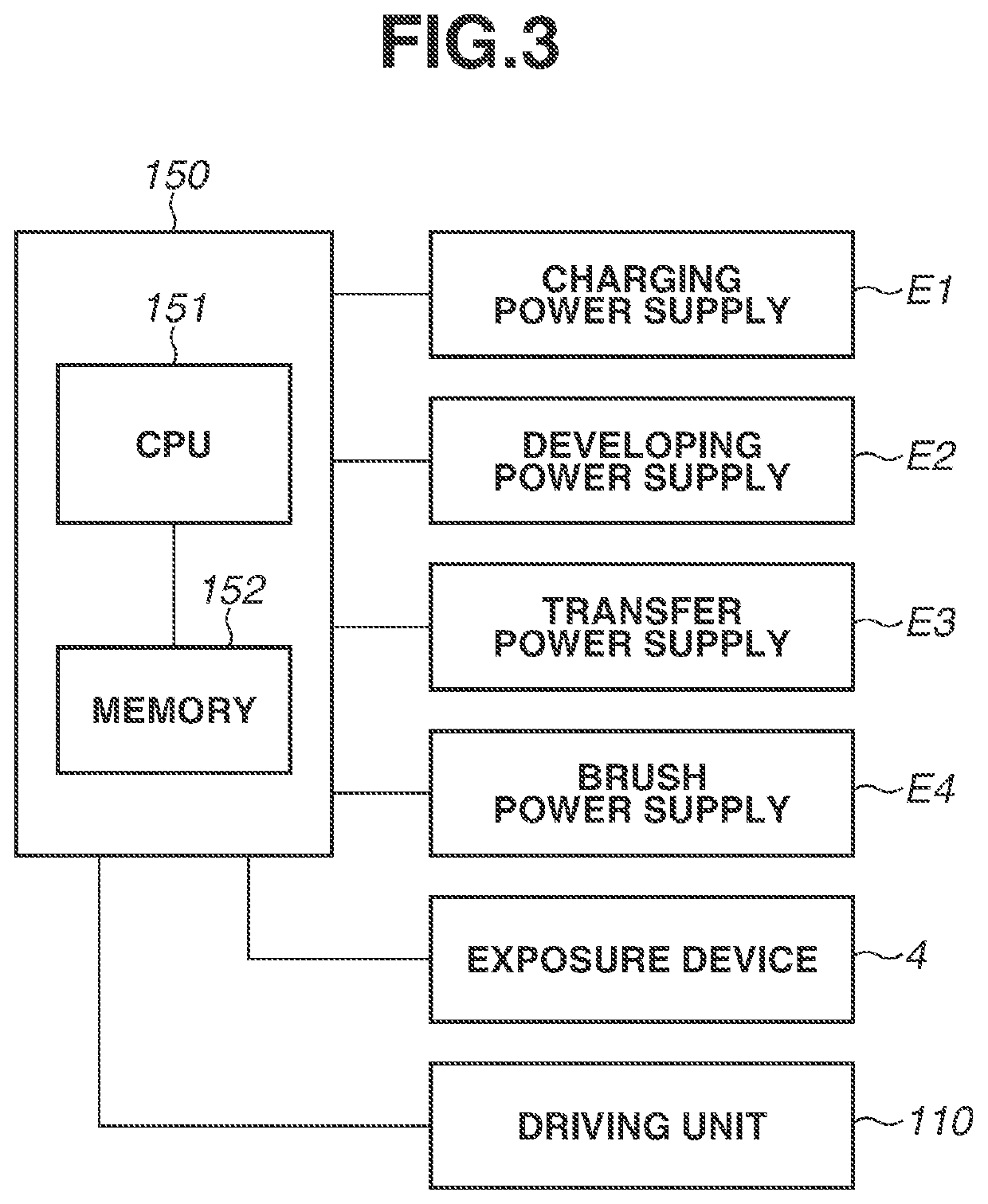
A driving unit is controlled so that a driving state where an image bearing member is driven with a first potential difference formed between a brush member and the image bearing member at a contact portion where the image bearing member is in contact with the brush member transitions to a stopped state where the image bearing member stops being driven with a second potential difference formed, the second potential difference having an absolute value less than that of the first potential difference.

Description

BACKGROUND OF THE DISCLOSUREField of the Disclosure[0001]The present disclosure relates to image forming apparatuses, such as laser printers, copying machines, and facsimiles, that obtain recorded images by transferring toner images formed on image bearing members in electrophotographic methods to recording materials.Description of the Related Art[0002]There are known electrophotographic methods as image recording methods for use in image forming apparatuses such as printers and copying machines. One electrophotographic method uses an electrophotographic process of forming an electrostatic latent image on a photosensitive drum (hereinafter, may be referred to as a drum) with laser beams, developing the electrostatic latent image with a charged coloring material (hereinafter, referred to as toner) to form a developer image, and then transferring and fixing the developer image to a recording material for image formation. In recent years, there has been proposed cleanerless methods for...

Claims


Application Information

Patent Timeline
IPC IPC(8): G03G21/00G03G21/10G03G15/08
CPCG03G21/0035G03G21/10G03G15/08G03G21/0005G03G15/50G03G15/065G03G21/0064G03G21/0023G03G15/5008
Inventor TAKAYAMA, TOSHIHIKOKOBAYASHI, SHINSUKETETSUNO, SHUICHIFUNATANI, KAZUHIROHARA, JUN
Owner CANON KK
Learn More