
A scope

Pending Publication Date: 2022-08-11
NATIONAL UNIVERSITY OF IRELAND
View PDF0 Cites 2 Cited by
  • Summary
  • Abstract
  • Description
  • Claims
  • Application Information

AI Technical Summary

Benefits of technology

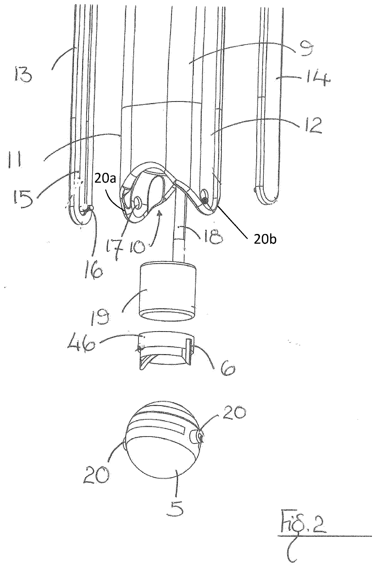
The invention is a probe with a camera that can be easily disassembled for cleaning and re-use. The probe has a distal opening that allows for increased visibility and a clear field of view. The opening is formed by a notch in the end of the probe, which allows the camera to have an unobstructed view in a direction back towards the proximal end of the probe. This makes it easier to clean and re-use the probe while maintaining its functionality.

Problems solved by technology

Hearing loss, complications of inflammation and complications of treatment are daily challenges and, as a result, patients with these conditions (children and adults) frequently require invasive ear surgery.
However, a major disadvantage of this approach is the narrow field of view looking down into the ear canal which can lead to poorer visualization of disease in difficult to access areas in the middle ear, such as the sinus tympani and facial recess.
However, mastoidectomy procedures are associated with increased operating times, more serious complications, longer hospital stays and protracted recovery for patients.
In addition, trans canal surgery is generally performed through a speculum by looking through the microscope and using specialized instruments resulting in a narrow field of view.
Moreover, due to the large size of the microscopic equipment employed in ear surgeries, negative ergonomic issues arise—the surgeon is forced into an extended position due to the size of the operating microscope which can compromise the dexterity required of the surgeon during surgical procedures.
Accordingly, when the scope is reoriented or rotated (perhaps for the comfort of the patient) the image observed also reorients or rotates which can result in disorientation of the user.
Moreover, in use, tissue can frequently adhere to scopes which can obscure vision with the result that the scope must regularly be removed from a subject's ear during surgery for cleaning which interrupts and prolongs the surgical procedure.
Overall, difficulties are encountered by surgeons visualising and focusing on the internal structures of the ear during surgery using known scopes in which the ability to accurately focus the scope and orient the scope for optimal viewing is absent.

Method used


Image

  • A scope
  • A scope
  • A scope

Examples


fourth embodiment

[0373]FIG. 17(a) is a side elevation of the scope 1 similar to the scope 1 of FIGS. 16(a) and 16(b) but in which, in addition to the elongate probe 2 being slidable and orientable, the elongate probe 2 is curved to conform with the wall 60 of the speculum 55 to create additional space in the speculum chamber 61 for a surgeon in use. The scope 1 is provided with a probe direction wheel 70 in place of the probe direction lever of FIG. 16(a).

[0374]FIG. 17(b) is a side elevation of the endoscope of FIG. 17(a) but in which the probe direction wheel 70 is replaced by a probe direction slider 71.

[0375]FIGS. 18(a) to 18(c) show side elevations of an embodiment of the invention similar to that of FIGS. 16 and 17 but in which the probe 2 is also slidable with respect to the speculum 2.

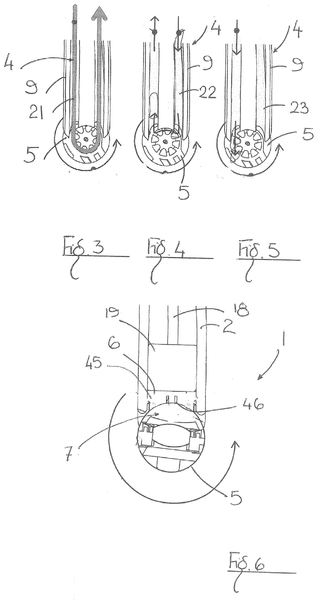
[0376]FIG. 19 is an enlarged cross-sectional view of a portion of the orienting mechanism 4 for the tiltable camera 52. As shown in the drawing, the probe orienting mechanism is made up of the tiltable camera 52...


PUM


Abstract

A scope (1) for examining or surgically treating ears comprising a probe (2); at least one visualiser (3) on the probe having an optical configuration (7), and a light source (42) wherein the visualiser (3) is articulatable about a visualiser articulation axis (3a) by an orienting mechanism (4) for optimal viewing of the ear.

Description

RELATED APPLICATIONS[0001]This application claims priority from EP19187833, the contents of which are hereby incorporated by reference.INTRODUCTION[0002]This invention relates to a scope and more particularly to a medical scope such as an otoscope or an endoscope for examining and surgically treating ears.BACKGROUND OF THE INVENTION[0003]Medical devices of various types are employed to examine and perform surgery on ears. For example, endoscopes and otoscopes (hereinafter referred to collectively as scopes) are instruments which are held against the eye to view and magnify the subject. These instruments have evolved with the addition of a camera so that the subject is viewed using a computer monitor or a video display.[0004]Recurrent acute otitis media, otitis media with effusion, chronic secretory / suppurative otitis media continues to impact quality of life for millions of patients world-wide. Hearing loss, complications of inflammation and complications of treatment are daily chal...

Claims


Application Information

Patent Timeline
IPC IPC(8): A61B1/227A61B1/00A61B1/05A61B1/06A61B1/12
CPCA61B1/227A61B1/00096A61B1/00183A61B1/121A61B1/00114A61B1/05A61B1/0627A61B1/00188A61B1/04A61B1/126A61B1/00172A61B1/00016A61B1/32A61B1/015A61B1/018A61B1/0684A61B1/0676A61B1/00193A61B1/00018A61B1/00029
Inventor O'CALLAGHAN, RORYKEOGH, IVANGALLAGHER, MARTINMCGLOUGHLIN, ELIZABETHWALSH, CHRISTINAO'HALLORAN, MARTINABBASI, JIBRAN AHMEDMCDERMOTT, BARRY
Owner NATIONAL UNIVERSITY OF IRELAND
Learn More