Construction machine

a construction machine and housing cover technology, applied in the field of construction machines, can solve the problems of difficult arrangement of the first control valve, the second control valve, the third control valve, and the largely blocked view range of the operator by the right front housing cover, so as to improve workability and easy to obtain

Active Publication Date: 2015-04-28
NIHON KENKI CO LTD
View PDF11 Cites 2 Cited by
  • Summary
  • Abstract
  • Description
  • Claims
  • Application Information

AI Technical Summary

Benefits of technology

[0009]In view of the above described conventional art problems, it is an object of the present invention to provide a construction machine that can improve a range of an operator's view when an operator looks visually ahead of a vehicle body on the right.
[0012]With this arrangement, the second control valve is arranged in the back side of the first control valve and in the upper side of the first control valve, and thereby the first control valve and the second control valve can be arranged to line up in the upper-lower direction. Therefore, as compared to a case where the first control valve and the second control valve are arranged to line up in the front-rear direction, a dimension of the right front housing cover that covers the valve accommodation room in the front-rear direction can be reduced to move (retract) a position of the front end portion of the right front housing cover to the backward side. On the other hand, by providing the right front housing cover along the virtual line extending in the oblique downward direction through the front end of the first control valve and the front end of the second control valve, an upper end side in the right front housing cover is inclined in an oblique downward direction from backward to forward. As a result, when an operator in the cab visually looks ahead of the vehicle body on the right, a range of view of the operator in the right-front side can be improved without largely blocking the range of view of the operator by the front end side of the right front housing cover.
[0014]With this arrangement, the upper end side of the right front housing cover can be inclined in the oblique downward direction from backward to forward, and the range of view of an operator can be improved when the operator in the cab looks ahead of the vehicle body on the right.
[0016]With this arrangement, the second control valve overlaps the rear portion side in the first control valve, which allows a space in the right front housing cover in the front-rear direction occupied by the first control valve and the second control valve to be small. As a result, the dimension of the right front housing cover in the front-rear direction can be made small to move the position of the front end portion in the right front housing cover to the backward side, and therefore a range of view of an operator ahead of the cab on the right can be improved.
[0022]With this arrangement, by providing the bracket on the first control valve and mounting the second control valve and the third control valve on the bracket, the second control valve and the third control valve can be simultaneously inserted in or removed from the first control valve by using the bracket to improve workability at the time of mounting the second control valve and the third control valve on the first control valve.
[0023](7) According to the present invention, a fuel tank is positioned in the back side of the right front housing cover at the right side of the vehicle body to form a rear surface of the valve accommodation room, and the right front housing cover is provided with a step which is a foothold for getting on the vehicle body. With this arrangement, an operator can easily get on the vehicle body by using the step provided in the right front housing cover as the foothold.

Problems solved by technology

In consequence, in the wheel type hydraulic excavator or in the backward-small revolving type hydraulic excavator, an accommodating space of equipments that is disposed in the front side of the engine is narrow, and therefore it is difficult to arrange the first control valve, the second control valve, the third control valve, and the like in this narrow accommodation space.
Therefore, when an operator in a cab looks visually in the right forward side, there is a problem that a range of view of the operator is largely blocked by the right front housing cover.

Method used


Image

  • Construction machine
  • Construction machine
  • Construction machine

Examples


Embodiment Construction

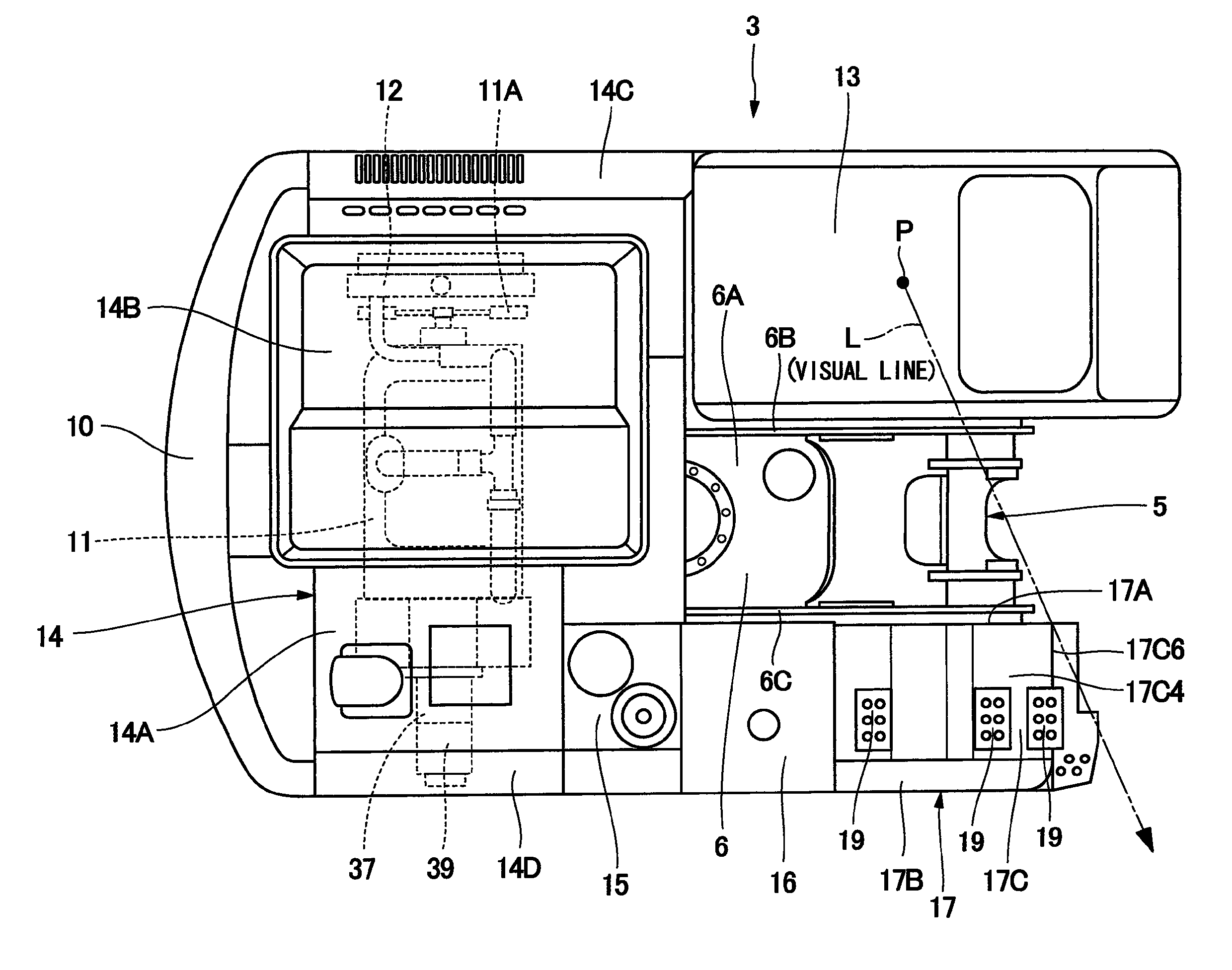
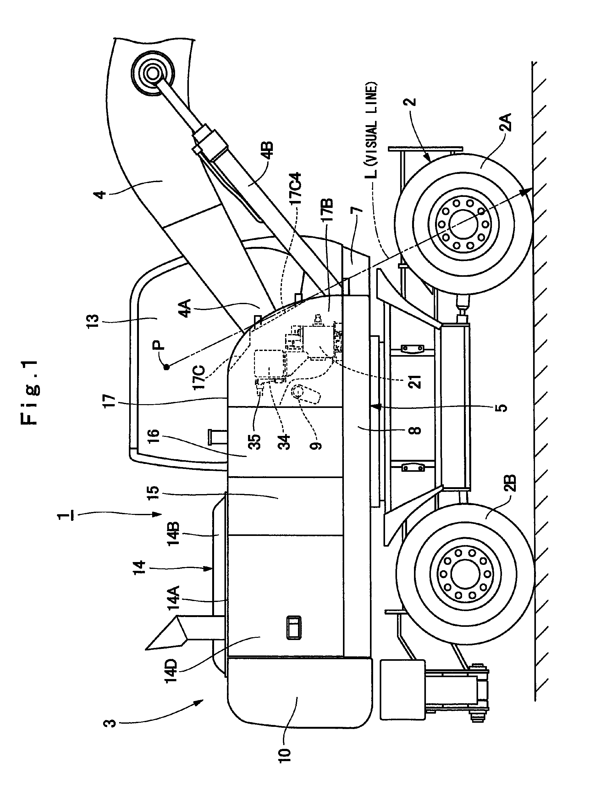
[0031]Hereinafter, an embodiment of a construction machine according to the present invention will be in detail explained with reference to FIG. 1 to FIG. 7 by taking a case of being applied to a wheel type hydraulic excavator as an example.

[0032]Designated at 1 is a wheel type hydraulic excavator as a construction machine. A vehicle body of the wheel type hydraulic excavator 1 is configured of a wheel type lower traveling structure 2 having right and left front wheels 2A and right and left rear wheels 2B, and an upper revolving structure 3 that is mounted on the lower traveling structure 2 to be capable of revolving thereon. A working mechanism 4 is tiltably provided in a front portion side of the upper revolving structure 3. The wheel type hydraulic excavator 1 travels on a public road by the lower traveling structure 2, and performs an excavating operation of earth and sand and the like by using the working mechanism 4 while revolving the upper revolving structure 3 at a working ...


PUM


Abstract

A right front housing cover is arranged in the right side of a working mechanism, and a first control valve is arranged in a front portion side of a valve accommodation room that is covered with the right front housing cover. Further, a signal control valve block is arranged in the back side of the first control valve and in the upper side of the first control valve, and a solenoid valve is arranged in the back side of the signal control valve block. A front surface plate forming part of the right front housing cover has a lower side is inclined in an oblique downward direction toward the forward side, and is arranged along a virtual line that extends in an oblique downward direction through a front end portion of the first control valve and a front end portion of the signal control valve block.

Description

TECHNICAL FIELD[0001]The present invention relates to a construction machine, such as a hydraulic excavator or a wheel type hydraulic excavator, and more particularly to a construction machine in which a control valve unit is arranged in a front portion right side in a vehicle body.BACKGROUND ART[0002]In general, a construction machine, such as a hydraulic excavator or a wheel type hydraulic excavator, has a vehicle body that is configured of an automotive lower traveling structure, and an upper revolving structure that is mounted on the lower traveling structure to be capable of revolving thereon. A working mechanism that performs an excavating operation or the like is tiltably provided in a front portion side of the upper revolving structure. The construction machine, after self-traveling to a working site, uses the working mechanism to perform an excavating operation of earth and sand or the like.[0003]Here, the construction machine is provided with a hydraulic motor for travelin...

Claims


Application Information

Patent Timeline
Patent Type & Authority Patents(United States)
IPC IPC(8): B62D23/00E02F9/08E02F9/22
CPCE02F9/2267E02F9/0833E02F9/0875E02F9/0883E02F9/2282E02F9/2285E02F9/2292E02F9/2296E02F9/08E02F9/0808E02F9/0891
Inventor OOTSUKA, KAKUROUHIRAMATSU, HIDEFUMIUEKI, TSUYOSHI
Owner NIHON KENKI CO LTD
Why Eureka
Try Eureka