Annular component for supporting a turbine engine bearing

Pending Publication Date: 2022-07-14
SAFRAN HELICOPTER ENGINES
View PDF0 Cites 0 Cited by
  • Summary
  • Abstract
  • Description
  • Claims
  • Application Information

AI Technical Summary

Benefits of technology

The present invention provides a simple and effective solution to overcome the drawbacks of the prior art by reducing the dimensions of the shells and eliminating the need for additional sealing elements. The corrugations create a non-axisymmetry, allowing for a localized state of thermomechanical stress that increases the robustness and longevity of the annular support component. The amplitude and position of the corrugations can be adjusted to achieve more or less non-axisymmetry and reinforce the mechanical strength or adjust the stiffness of the bearing support assembly.

Problems solved by technology

In the case of annular components for supporting the rear bearing(s), these are subject to relatively high thermal stresses.
This also results in a loss of performance of the turbine engine due to a less robust and unreliable sealing.
In addition, the sealing elements add space and design constraints of the annular component.
Another drawback of this type of annular component is that there is a quasi-axisymmetric stress field at the axisymmetric shells of the component, even in the presence of the radial arms.
As a result, rapid crack propagation after a fatigue initiation phase can lead to the failure of the annular component and thus the loss of the holding of the rotating elements of the bearing housing.
Finally, an annular bearing support component is complex to produce, particularly by the casting technique, and therefore has a high manufacturing cost.
In addition, its mechanical reliability in operation can also lead to significant additional costs, which result either in numerous repairs or in premature disposal.
In addition, this annular component presents assembly constraints (in particular by its axial root) with the other elements of the environment (shaft, fixing flanges, auxiliary ducts, etc.).

Method used


Image

  • Annular component for supporting a turbine engine bearing
  • Annular component for supporting a turbine engine bearing
  • Annular component for supporting a turbine engine bearing

Examples


first embodiment

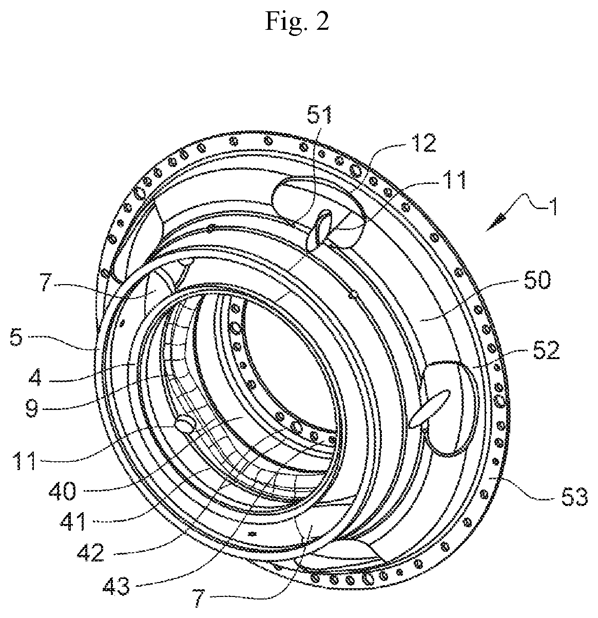
[0044] the component 1 has a shape of revolution extending around an axis which is coincident with the axis X-X of the turbine engine.

[0045]With reference to FIG. 2, the component 1 comprises two annular walls, respectively internal 4 and external 5, which are connected to each other by arms 7. These arms 7 may be solid or tubular (or otherwise said to be hollow) for example for the passage of auxiliaries 8. This component 1 further comprises an internal annular shell 40 extending radially inside the internal annular wall 4 and an external annular shell 50 which extends around the external annular wall 5.

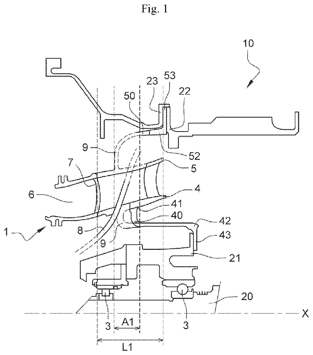
[0046]The internal annular shell 40 comprises an external peripheral edge 41 connected to the internal annular wall 4 and an internal peripheral edge 42 coprising an internal fixing flange 43. This internal flange 43 may be connected by fastening means (such as bolts) to a flange of the internal structure 21 of the turbine engine 10, as shown for example in FIG. 1.

[0047]The external...

second embodiment

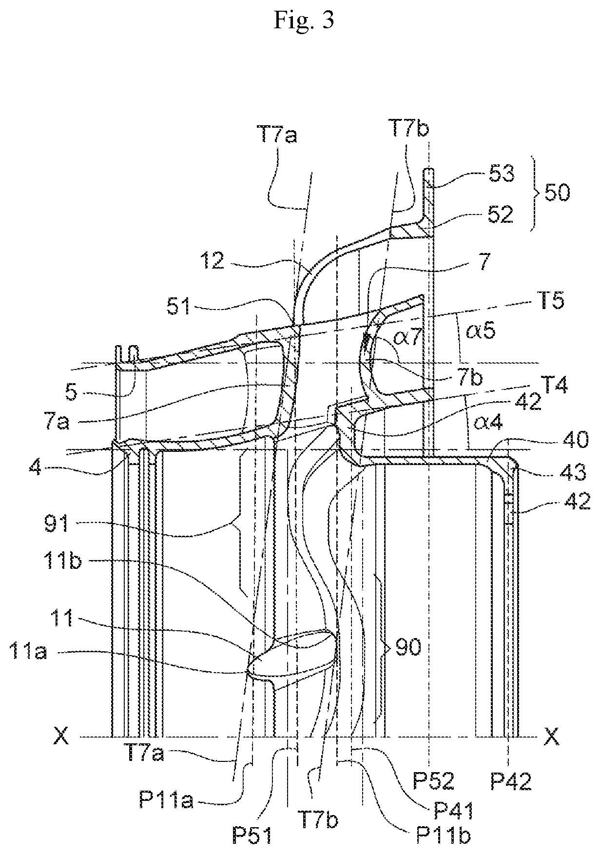
[0060]FIGS. 4 and 5 illustrate the The component 2 is distinguished from the component 1 by the external edge 41 connected to the annular wall4 which has a generally circular shape, whereas the internal edge 51 comprises corrugations 9 arranged around the axis X-X. This corrugated edge 51 extends in a plane P51 downstream of the component 2 and perpendicular to the axis X-X, and the external edge 52 extends in a plane P52 upstream which is parallel to P51. The internal shell 40 comprises openings 12 which are through openings and which are substantially radially aligned with the arms 7. The annular walls 4, 5 comprise holes 11 which are through holes and which open into the arms 7. The arms 7, the openings 12 and the holes 11 are also at least partially radially aligned with each other to allow the passage of auxiliaries 8. The openings 12 are different in shape and size from the holes 11.

[0061]The holes 11 in the external annular wall 5 are elongate in shape similar to an aircraft...


PUM


Abstract

A component (1, 2) for supporting at least one bearing (3) for a turbine engine (10) comprising: two coaxial walls, internal (4) and external (5) walls respectively, defining a gas flow vein (6) between them and interconnected by a row of arms (7); an external ferrule (50) comprising an internal peripheral edge (51) connected to the external wall (5) and an external peripheral edge (52) connected to an external mounting flange (53); an internal ferrule (40) comprising an external peripheral edge (41) connected to the internal wall (4) and an internal peripheral edge (42) comprising an internal mounting flange (43); at least one of the ferrules (4, 5), which at the peripheral edge (41, 51) thereof is connected to the corresponding wall (4, 5), having a general shape which is corrugated about an axis (X-X) of the component (1, 2).

Description

TECHNICAL FIELD OF THE INVENTION[0001]The field of the present invention is that of aeronautical turbine engines and more particularly that of their components participating in the support of the bearings of their shaft.BACKGROUND[0002]Aeronautical turbine engines, whether single or multi-spools, generally comprise one or more structural annular components, also known as bearing supports, which support the bearing(s) on which the rotating shafts of these spools rotate. Such annular components may support the power shaft driven by a free turbine in the case of a turbine engine. Such annular components may also provide a seal between the free turbine (FT) and High Pressure (HP) stages.[0003]In the case of annular components for supporting the rear bearing(s), these are subject to relatively high thermal stresses. In fact, they are attached to an external structure of the engine by a flange which is located in a cold zone; whereas their median part, in the form of a channel, is travers...

Claims


Application Information

Patent Timeline
IPC IPC(8): F01D25/16F01D25/28
CPCF01D25/162F01D25/28F05D2220/323F05D2260/30F05D2250/61F05D2250/141F05D2250/291F05D2240/50F02C7/06F01D9/041F01D25/164F05D2250/18F05D2250/183F05D2250/184
Inventor JOSSE, ALBERTVIVE, LOIS PIERRE DENISCASAUX-BIC, JEAN-MAURICELAMEIGNERE, YVAN LUDOVIC
Owner SAFRAN HELICOPTER ENGINES
Why Eureka
Try Eureka