Aircraft turbomachine with mechanical reducer and contrarotative turbine

a technology of mechanical reducer and turbine, which is applied in the manufacture of engines, machines/engines, mechanical apparatuses, etc., can solve the problems of complex structure, complicated design, and restricted shaft passage through restricted areas

Active Publication Date: 2022-08-16
SN DETUDE & DE CONSTR DE MOTEURS DAVIATION S N E C M A
View PDF16 Cites 0 Cited by
  • Summary
  • Abstract
  • Description
  • Claims
  • Application Information

AI Technical Summary

Benefits of technology

[0011]This disclosure provides a simple, effective and economical solution to at least some of the problems mentioned above.
[0013]The disclosure provides for the assembly and disassembly of a turbomachine with counter-rotating turbine. The nut facilitates this assembly and disassembly. It can cooperate with surrounding parts to trap it in a cavity during an assembly / disassembly phase which can often be carried out blindly. The nut preferably remains trapped in the cavity until the first shaft is removed. Its arrangement allows two coaxial shafts with very similar diameters while allowing disassembly by functional sub-assemblies.
[0019]The disclosure thus offers an optimal arrangement of the bearings in a turbomachine with counter-rotating turbine and reducer.

Problems solved by technology

However, increasing the rotational speed of the turbine implies increasing the centrifugal forces it undergoes, and therefore greatly complicates its design.
This architecture is complex due to its mechanical integration: the mechanical reducer is located upstream of the low-pressure compressor.
These shafts pass through very restricted areas.
Finally, the assembly and disassembly of such an engine is particularly complex.

Method used


Image

  • Aircraft turbomachine with mechanical reducer and contrarotative turbine
  • Aircraft turbomachine with mechanical reducer and contrarotative turbine
  • Aircraft turbomachine with mechanical reducer and contrarotative turbine

Examples


Embodiment Construction

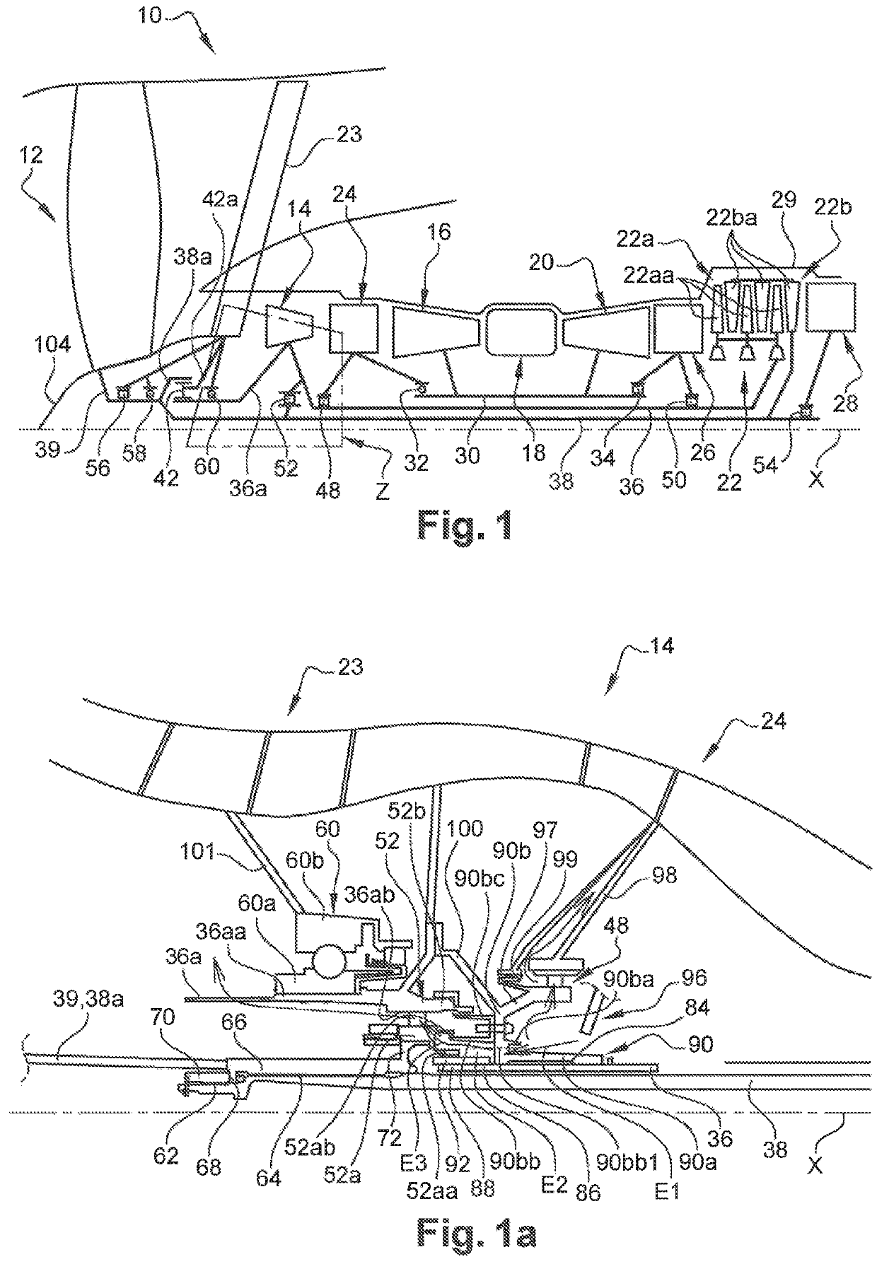
[0033]FIG. 1 shows a very schematic representation of a turbomachine 10 with counter-rotating turbine and reducer for an aircraft.

[0034]This turbomachine 10 includes, from upstream to downstream, in the direction of flow of gases, a fan 12, a low-pressure compressor 14, a high-pressure compressor 16, an annular combustion chamber 18, a high-pressure turbine 20 and a counter-rotating turbine 22.

[0035]The reference 23 refers to an input casing located between the fan 12 and the compressor 14. The reference 24 refers to an intermediate casing located between the compressors 14 and 16, and the reference 26 refers to a turbine casing (TVF type) located between the turbines 20 and 22. Finally, the reference 28 refers to an exhaust casing (TRF type).

[0036]The rotor of the high-pressure turbine 20 drives the rotor of the high-pressure compressor 16 in rotation by a high-pressure shaft 30 which is centered and guided in rotation by bearings, such as an upstream ball bearing 32 and a downstre...


PUM


Abstract

Aircraft turbomachine with mechanical reducer and counter-rotating turbine are described. The turbomachine includes a fan driven in rotation by a fan shaft, a mechanical reducer with epicyclic gear train, a gas generator comprising a counter-rotating turbine, a first turbine shaft of which is coupled to an input shaft of the reducer and to a pin, and a second turbine shaft of which is coupled to the fan shaft. The guidance of the reducer input shaft is provided by a first ball bearing, the guidance of the pin is provided by a second roller bearing, and the guidance of the first shaft is provided by a third roller bearing axially interposed between the first and second bearings.

Description

TECHNICAL FIELD[0001]The present disclosure relates to a counter-rotating turbine turbomachine for an aircraft.BACKGROUND[0002]The prior art includes documents FR-A1-2 942 273, FR-A1-2 641 331 and FR-A1-2 641 333.[0003]Typically, an aircraft turbomachine includes, from upstream to downstream, in the direction of the flow of gases, a fan, a low-pressure compressor, a high-pressure compressor, an annular combustion chamber, a high-pressure turbine, and a low-pressure turbine. The low-pressure compressor rotor is driven by the low-pressure turbine rotor, and the high-pressure compressor rotor is driven by the high-pressure turbine rotor.[0004]From the point of view of engine performance and fuel consumption, it is advantageous to maximize the rotational speed of the low-pressure turbine because this achieves better turbine efficiency. However, increasing the rotational speed of the turbine implies increasing the centrifugal forces it undergoes, and therefore greatly complicates its des...

Claims


Application Information

Patent Timeline
Patent Type & Authority Patents(United States)
IPC IPC(8): F02C3/067F02C7/06F02C7/36F01D25/16
CPCF02C3/067F01D25/16F02C7/06F02C7/36F05D2220/323F05D2230/60F05D2240/50F05D2250/44F05D2260/40311F02K3/06
Inventor LEVISSE, PAUL GHISLAIN ALBERTBELMONTE, OLIVIERFORMICA, OLIVIER
Owner SN DETUDE & DE CONSTR DE MOTEURS DAVIATION S N E C M A
Why Eureka
Try Eureka