
Battery Module and Battery Pack Including the Same

a battery module and battery pack technology, applied in the direction of batteries, cell components, electrochemical generators, etc., can solve the problems of slow charging and discharging, ignition, explosion, accelerate the deterioration of battery cells, etc., and achieve the effect of effective cooling and heating of the battery modul

Pending Publication Date: 2022-06-23
LG ENERGY SOLUTION LTD
View PDF3 Cites 0 Cited by
  • Summary
  • Abstract
  • Description
  • Claims
  • Application Information

AI Technical Summary

Benefits of technology

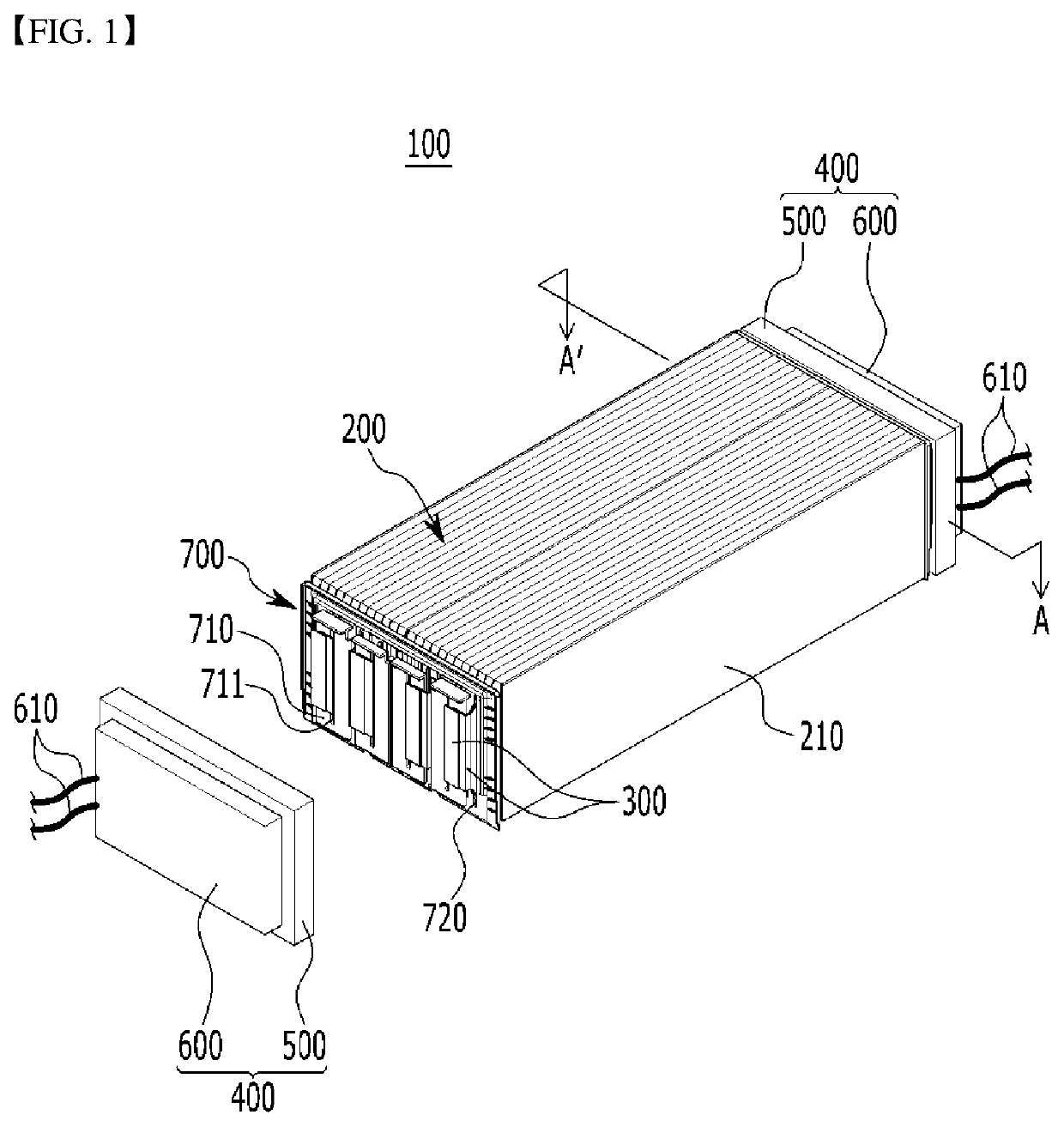
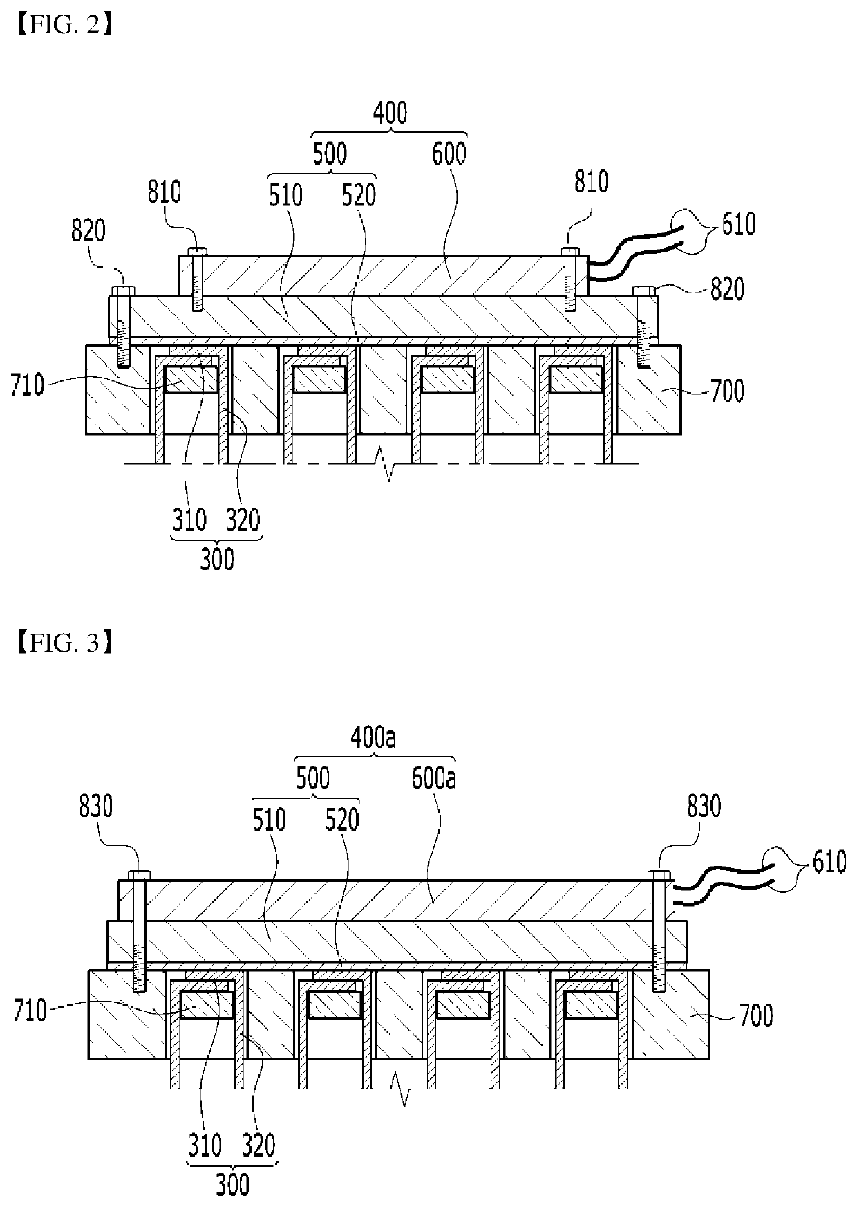
The present patent relates to a temperature control unit for battery modules. The unit can make direct contact with the electrode leads through a metal oxide layer, enabling effective cooling and heating of the module. The temperature control unit can be easily attached to make close contact with the electrode leads. The unit includes a thermoelectric element, allowing both cooling and heating of the battery module depending on the direction of applied electric power. The technical effect of this patent is to improve the performance and efficiency of battery modules by controlling their temperature.

Problems solved by technology

In this case, a plurality of battery cells generate heat during the charge or discharge process, and when the heat is not rapidly discharged in a dense state, it may accelerate deterioration of the battery cells and cause ignition, explosion or the like.
Meanwhile, when the plurality of battery cells are exposed to a low temperature environment, they have the feature that charging and discharging do not proceed smoothly due to the increase in resistance, and the output voltage and current decrease sharply.
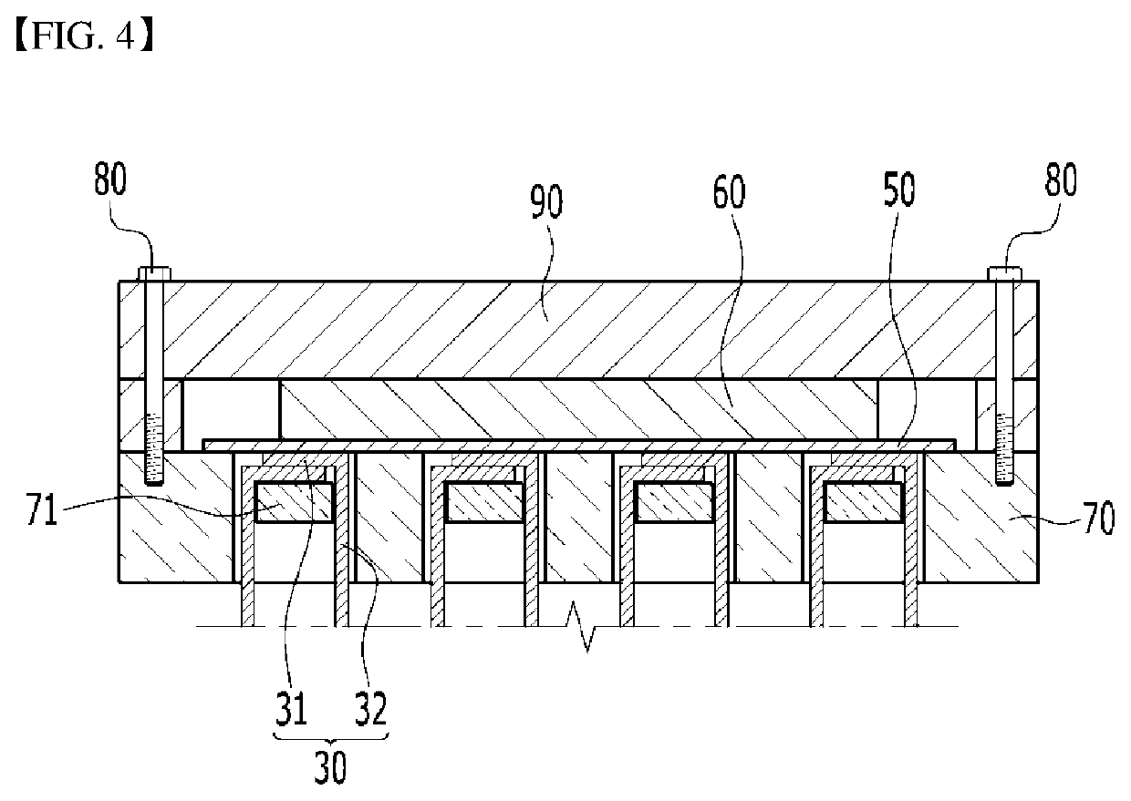
Here, there is a risk, such as a short circuit, in directly cooling or heating the electrode leads of the battery cells or the busbars connected to the electrode leads, and thus the cooling plate, in which an internal refrigerant circuit is formed, may be located on an opposite side to the electrode leads.
However, when the refrigerant leaks from an interior of the cooling plate, smooth cooling is difficult, and the leaked refrigerant may cause a danger such as a short circuit phenomenon.
Further, since it is not a structure that directly cools the electrode leads, in which the actual heat is generated, there must be inevitably some limitation in the cooling efficiency.

Method used


Image

  • Battery Module and Battery Pack Including the Same
  • Battery Module and Battery Pack Including the Same
  • Battery Module and Battery Pack Including the Same

Examples


Embodiment Construction

Technical Problem

[0010]Embodiments of the present disclosure have been made in an effort to solve the above-mentioned problems, and provide a battery module that includes a temperature control unit making contact with the electrode leads to enable effective cooling and heating, and a battery pack including the same. However, the problem to be solved by the embodiments of the present disclosure is not limited to the above-described problems, and can be variously expanded within the scope of the technical idea included in the present disclosure.

Technical Solution

[0011]A battery module according to an embodiment of the present disclosure includes a battery cell stack, in which a plurality of battery cells comprising electrode leads, are stacked; a busbar connecting the electrode leads; and a temperature control unit that makes contact with the electrode leads, the temperature control unit includes a heat transfer member that makes contact with the electrode leads and a thermoelectric e...


PUM

PropertyMeasurementUnit
thicknessaaaaaaaaaa
thicknessaaaaaaaaaa
thicknessaaaaaaaaaa

Abstract

The battery module according to one embodiment of the present disclosure includes: a battery cell stack, in which a plurality of battery cells comprising electrode leads, are stacked; busbars connecting the electrode leads; and a temperature control unit that makes contact with the electrode leads. The temperature control unit comprises a heat transfer member that makes contact with the electrode leads and a thermoelectric element capable of being heated and cooled, wherein the heat transfer member comprises a metal layer and a metal oxide layer, the metal oxide layer being located between the metal layer and the electrode leads.

Description

CROSS-REFERENCE TO RELATED APPLICATIONS[0001]This application is a national phase entry under 35 U.S.C. § 371 of International Application No. PCT / KR2020 / 008519 filed on Jun. 30, 2020, which claims priority from Korean Patent Application No. 10-2019-0125309 filed on Oct. 10, 2019, the disclosure of which is incorporated herein by reference in its entirety.TECHNICAL FIELD[0002]The present disclosure relates to a battery module and a battery pack including the same, and more particularly to a battery module having improved temperature control performance, and a battery pack including the same.BACKGROUND ART[0003]In modern society, as portable devices such as mobile phones, notebook computers, camcorders and digital cameras have been daily used, the development of technologies in the fields related to mobile devices as described above has been activated. In addition, rechargeable batteries are used as a power source for electric vehicles (EV), hybrid electric vehicles (HEV), plug-in hy...

Claims


Application Information

Patent Timeline
Patent Type & Authority Applications(United States)
IPC IPC(8): H01M10/6572H01M50/507H01M50/536H01M10/653
CPCH01M10/6572H01M10/653H01M50/536H01M50/507H01M10/613H01M10/615H01M10/6553H01M50/258H01M50/204Y02E60/10H01M50/505H01M50/557H01M10/63H01M10/6554H01M50/502H01M50/20H01M10/625H01M2220/20Y02T10/70
Inventor YUN, SUNWOOKIM, MINJUNLEE, CHANGBOK
Owner LG ENERGY SOLUTION LTD
Learn More