
Touch display device and touch sensing circuit

a touch display device and touch sensing technology, applied in electronic switching, pulse technique, instruments, etc., can solve the problems of degrading the touch accuracy of the touch display device, and achieve the effect of improving the resistance to electromagnetic noise, increasing the touch accuracy, and removing electromagnetic nois

Active Publication Date: 2022-06-16
LG DISPLAY CO LTD
View PDF4 Cites 0 Cited by
  • Summary
  • Abstract
  • Description
  • Claims
  • Application Information

AI Technical Summary

Benefits of technology

The present patent is about a touch display device and a touch sensing circuit that can improve resistance to electromagnetic noise and remove electromagnetic noise to increase touch accuracy. This can be achieved by lowering a cutoff frequency without adding a capacitor element.

Problems solved by technology

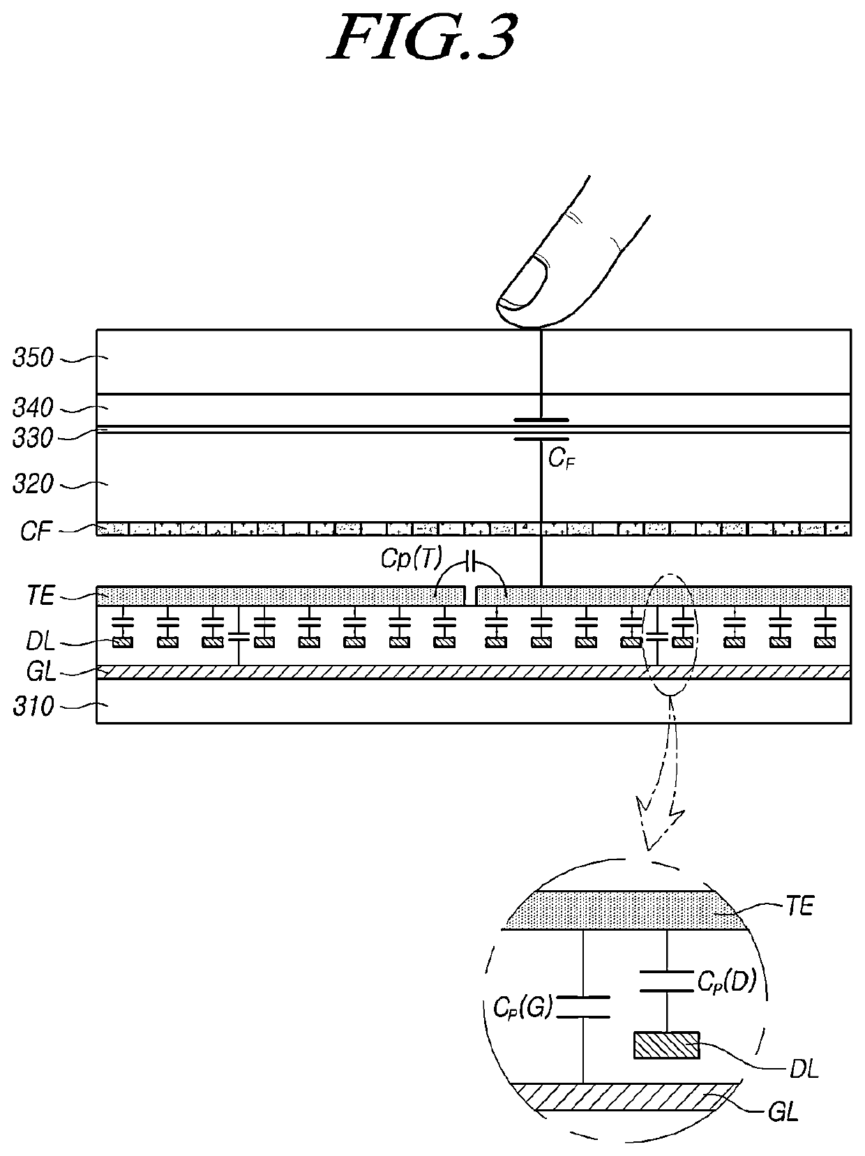
When electronic devices are adjacent to the touch display device, touch accuracy of the touch display device may be degraded due to electromagnetic wave noise emitted from not only the touch display device but also the surrounding electronic devices.

Method used


Image

  • Touch  display  device  and  touch  sensing  circuit
  • Touch  display  device  and  touch  sensing  circuit
  • Touch  display  device  and  touch  sensing  circuit

Examples


Embodiment Construction

[0044]In the following description of examples or embodiments of the present invention, reference will be made to the accompanying drawings in which it is shown by way of illustration specific examples or embodiments that can be implemented, and in which the same reference numerals and signs can be used to designate the same or like components even when they are shown in different accompanying drawings from one another. Further, in the following description of examples or embodiments of the present invention, detailed descriptions of well-known functions and components incorporated herein will be omitted when it is determined that the description may make the subject matter in some embodiments of the present invention rather unclear. The terms such as “including”, “having”, “containing”, and “constituting” used herein are generally intended to allow other components to be added unless the terms are used with the term “only”. As used herein, singular forms are intended to include plu...


PUM


Abstract

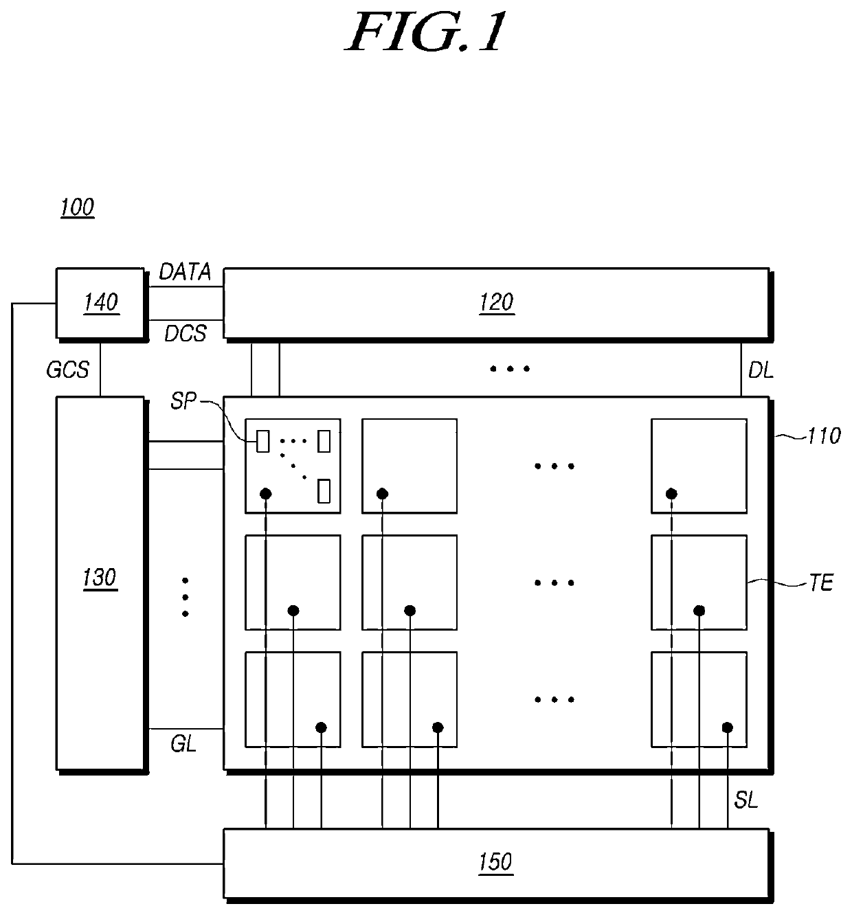
Embodiments of the present disclosure relate to a touch display device and a touch sensing circuit that apply a load-free driving signal having a phase difference or amplitude difference from the touch driving signal to a touch display panel. According to embodiments of the present disclosure, electromagnetic noise immunity may be improved and touch accuracy may be increased. The touch sensing circuit comprises: a touch driving circuit configured to output a pulse type touch driving signal to at least one of a plurality of touch electrodes disposed on a touch display panel; and a load-free driving signal output circuit configured to output at least one load-free driving signal having a frequency equal to a frequency of the touch driving signal and having a phase difference or amplitude difference from the touch driving signal.

Description

CROSS-REFERENCE TO RELATED APPLICATIONS[0001]This application claims the benefit and priority from Korean Patent Application No. 10-2020-0176069, filed in the Republic of Korea on Dec. 16, 2020, the entire contents of which are hereby incorporated by reference for all purposes as if fully set forth into the present application.BACKGROUNDTechnical Field[0002]Embodiments of the present disclosure relate to a touch display device and a touch sensing circuit.Discussion of the Related Art[0003]As the information society develops, demands for a display device for displaying an image are increasing in various forms, and in recent years, various display devices such as a liquid crystal display device and an organic light emitting display device are used.[0004]Recently, a touch display device that provides an easy touch input method in a display has been utilized, breaking away from the conventional input method such as a button, a mouse, and a keyboard.[0005]The touch display device has hig...

Claims


Application Information

Patent Timeline
Patent Type & Authority Applications(United States)
IPC IPC(8): G06F3/041G09G3/20
CPCG06F3/0418G09G2310/08G09G3/20G06F3/04182G06F3/0448G06F3/0412G06F3/0443G06F3/04166G06F3/04184G06F3/044H03K17/962H03K2217/96072
Inventor LEE, JEONGSEOPBYUN, SUNGUKJEONG, WOORIMYANG, HANKYU
Owner LG DISPLAY CO LTD
Learn More