
Wing model for static aeroelasticity wind tunnel test

a technology of aeroelasticity and wind tunnel, applied in the field of aeroelasticity test, can solve the problem of not having the capability of measuring real-time pressure distribution data, and achieve the effect of accurate aerodynamic data and high-strength loading capacity

Pending Publication Date: 2022-06-16
DALIAN UNIV OF TECH
View PDF8 Cites 1 Cited by
  • Summary
  • Abstract
  • Description
  • Claims
  • Application Information

AI Technical Summary

Benefits of technology

The present patent provides a wing model for a wind tunnel test that can measure changes in pressure distribution in real time during deformation under force. This allows for the accurate measurement of aerodynamic data. The model has a high-precision shape and strength and is made using a composite material skin and integrated force and pressure measurement. It is lightweight and easy to assemble for use in static aeroelasticity wind tunnel tests.

Problems solved by technology

Furthermore, the models are only used to research the static aeroelasticity property, and do not have the capability of measuring real-time pressure distribution data during the wind tunnel test.

Method used


Image

  • Wing model for static aeroelasticity wind tunnel test
  • Wing model for static aeroelasticity wind tunnel test
  • Wing model for static aeroelasticity wind tunnel test

Examples


Embodiment Construction

[0018]The structure of the disclosure will be further described below with reference to the drawings.

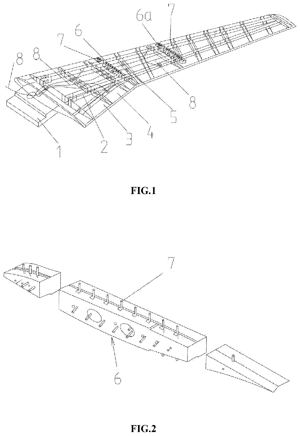
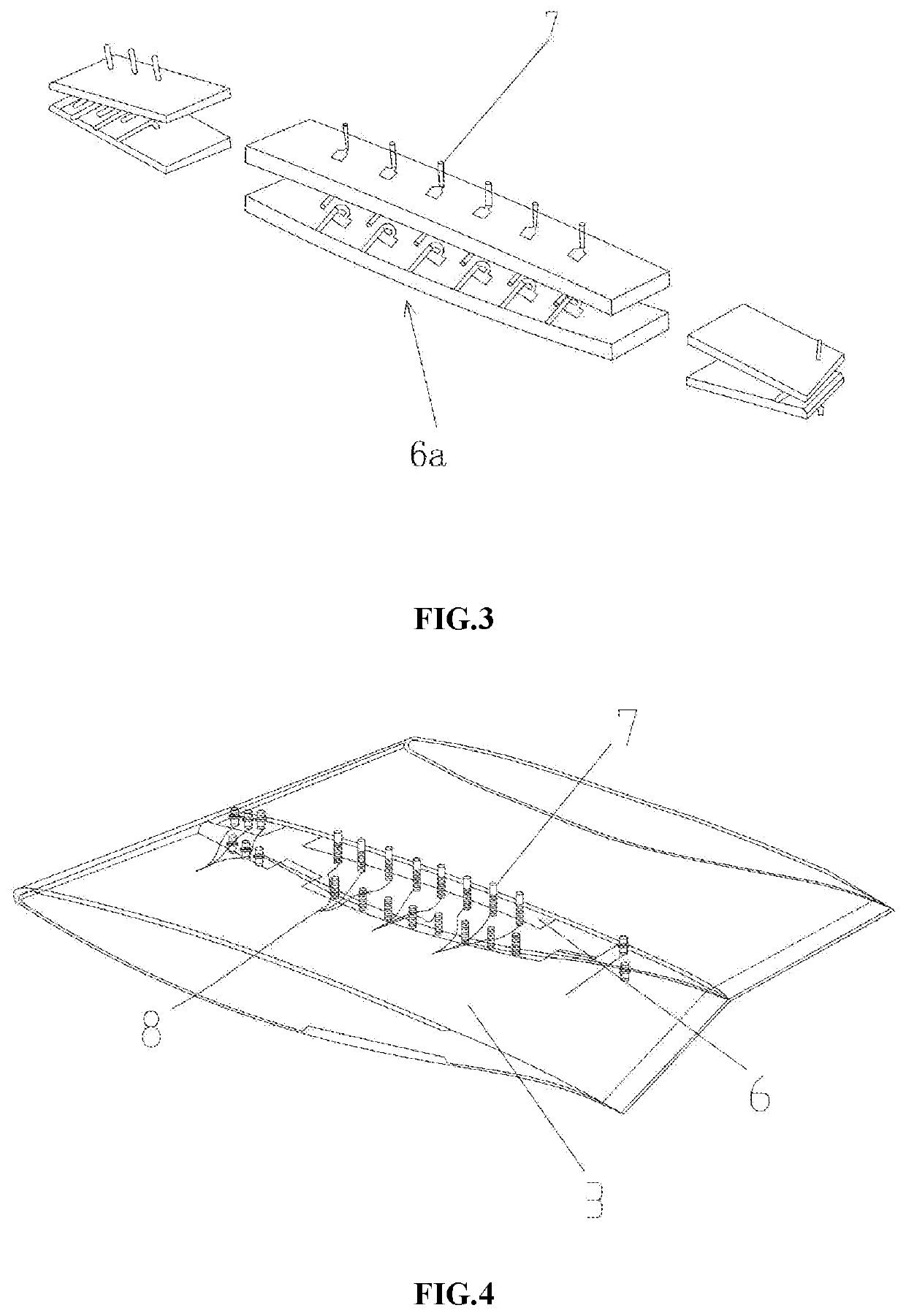
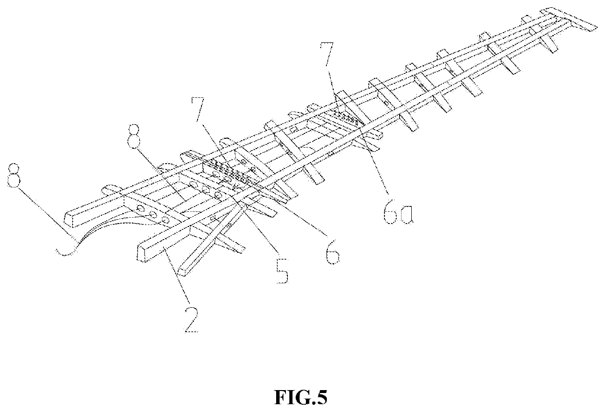
[0019]FIGS. 1, 4 and 5 show a schematic structural diagram of a wing model for a static aeroelasticity wind tunnel test. In the figures, the wing model for a static aeroelasticity wind tunnel test includes a model steel joint 1, a spar frame 2, a composite material skin 3, lightweight filling foam 4, a plurality of supporting wing ribs 5, two piezometer wing ribs, embedded piezometer tubes 7, and piezometer wires 8. The model steel joint 1 and the spar frame 2 are connected with the composite material skin 3. A structure of the spar frame 2 is in a form of two main beams and a single auxiliary beam. The piezometer ribs are arranged in the spare frame 2 and 12 supporting wing ribs 5. The embedded piezometer tubes 7 are arranged in the piezometer ribs. The lightweight filling foam 4 is arranged among the spare frame 2 and 12 supporting wing ribs 5. An outer surface of a frame segment f...


PUM


Abstract

A wing model for static aeroelasticity wind tunnel test belongs to the technical field of aeroelasticity tests. In the wing model, the model steel joint and the spar frame are connected with the composite material skin. The piezometer wing ribs are arranged among the spar frame and the plurality of supporting wing ribs. The embedded piezometer tubes are arranged in the piezometer wing ribs, the lightweight filling foam is arranged among the spar frame and the plurality of supporting wing ribs. An outer surface of a frame segment formed by the lightweight filling foam, the plurality of supporting wing ribs, the piezometer wing ribs and the spar frame is covered with the composite material skin. The frame segment is assembled on the model steel joint to form the wing model for the static aeroelasticity wind tunnel test.

Description

TECHNICAL FIELD[0001]The disclosure relates to the technical field of aeroelasticity test, and in particular to a wing model for a static aeroelasticity wind tunnel test capable of force and pressure measurement.BACKGROUND ART[0002]Traditional wing models for static aeroelasticity wind tunnel tests generally do not have a pressure measurement capability, and there is no specific accuracy requirement for the profile of the wing models. Furthermore, the models are only used to research the static aeroelasticity property, and do not have the capability of measuring real-time pressure distribution data during the wind tunnel test. However, with the continuous development of the high aspect ratio wing technology, the static aeroelasticity effect has become more prominent, and researchers have increasing requirements for the accuracy of aerodynamic data. By measuring the real-time pressure distribution data of the static aeroelasticity model during the wind tunnel test, it is possible to ...

Claims


Application Information

Patent Timeline
Patent Type & Authority Applications(United States)
IPC IPC(8): G01M9/08
CPCG01M9/08Y02T90/00
Inventor QIAN, WEIXIAO, LINGLI, XINGGE, SHAOJIEFENG, WEIZHEAI, XINYU
Owner DALIAN UNIV OF TECH
Learn More