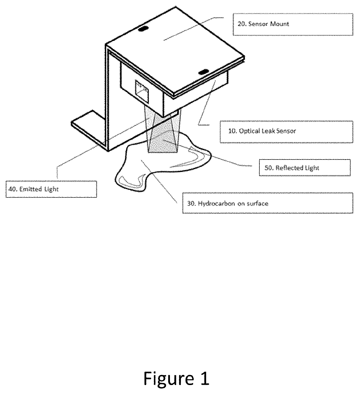
Optical Hydrocarbon Leak Detection Sensor

a technology of leak detection and optical hydrocarbon, which is applied in the direction of fluid/vacuum leakage detection, fluid tightness measurement using fluid/vacuum, electric transmission signalling system, etc., can solve the problems of long time of cable contact, safety and re-usability, security risk, etc., and achieve the effect of reducing cost and fast detection method

Pending Publication Date: 2022-06-16
VAN LAERE MAARTEN
View PDF2 Cites 0 Cited by
  • Summary
  • Abstract
  • Description
  • Claims
  • Application Information

AI Technical Summary

Benefits of technology

[0010]The main object is to provide a fast method for detecting hydrocarbon on surfaces. Current leak detection solutions rely on slow hydrocarbon sensitive leak cables or similar.
[0011]Another object is to provide a new method that allows for a hydrocarbon leak sensor to be reused compared to current solutions which are typically single use only. This makes the invention a lower cost alternative compared to current alternatives.
[0012]Another object is to provide a method is to enable the commissioning of hydrocarbon leak detection systems in a more reliable way by enabling to test the complete setup and then leave it as is without needing the replace the leak sensitive cable or device.

Problems solved by technology

Most leak detection solutions are very whereby it may require a long time of the cable being in contact with the hydrocarbon.
This has two major disadvantages: safety and re-usability.
Hydrocarbons are flammable and contact with electronics may cause a security risk.
While most solutions carry fire safety certifications, a risk can't be excluded.
The second disadvantage is that most of current solutions compared to the invention are single use.
This poses a major problem to installers.
It prevents installers to do a correct commission of a leak monitoring system as the hydrocarbon leak detector cannot be tested without requiring replacement.

Method used


Image

  • Optical Hydrocarbon Leak Detection Sensor

Examples


Embodiment Construction

[0022]In the following detailed description of the present invention of exemplary embodiments of the present invention, reference is made to the accompanying drawings (where like numbers represent like elements), which form a part hereof, and in which is shown by way of illustration specific exemplary embodiments in which the present invention may be practiced. These embodiments are described in sufficient detail to enable those skilled in the art to practice the present invention, but other embodiments may be utilized and logical, mechanical, electrical, and other changes may be made without departing from the scope of the present invention. The following detailed description is, therefore, not to be taken in a limiting sense, and the scope of the present invention is defined only by the appended claims.

[0023]In the following description, numerous specific details are set forth to provide a thorough understanding of the present invention. However, it is understood that the present ...


PUM

PropertyMeasurementUnit
reflective light spectrum analyzeraaaaaaaaaa
reflectivityaaaaaaaaaa
reflectionaaaaaaaaaa

Abstract

A method to have a fast, contactless & re-usable sensor to detect the presence of hydrocarbons on surfaces by analyzing the reflected light of the sensor. The invention generally is a sensor device which includes a light emitting source, a reflective light spectrum analyzer which is able to detect the specificity of the reflectivity of hydrocarbons on surfaces.

Description

TECHNICAL FIELD OF THE PRESENT INVENTION[0001]The present invention relates generally to a new, simple, fast, safe, re-usable and cost-effective way to detect the presence of hydrocarbons. More specifically the present invention relates to a method to have a fast, contactless & re-usable sensor to detect the presence of hydrocarbons on surfaces by analyzing the reflected light of the sensor. The invention generally is a sensor device which includes a light emitting source, a reflective light spectrum analyzer which is able to detect the specificity of the reflectivity of hydrocarbons on surfaces.BACKGROUND OF THE PRESENT INVENTION[0002]Industrial applications using in their operations equipment that use hydrocarbons in them, may require monitoring for any leak. This is typically done by using a sensor or device that has a specific cable which is sensitive to hydrocarbons. The cable is laid on the surface to be monitored. When the cable comes into contact with a hydrocarbon then the ...

Claims


Application Information

Patent Timeline
Patent Type & Authority Applications(United States)
IPC IPC(8): G01M3/04G08B7/06
CPCG01M3/04G08B7/06G01M3/38
Inventor VAN LAERE, MAARTEN
Owner VAN LAERE MAARTEN
Why Eureka
Try Eureka