
Safety lock mechanisms for portable weapons, including crossbows and firearms, such as guns, rifles and alike

a safety lock and portable technology, applied in the direction of weapons, weapon components, safety arrangements, etc., can solve the problems of not being able to provide any solution for instantaneously blocking the firing sequence, prior attempts would not allow/enable to provide means to promptly lock and unlock the firing sequence, automatically or autonomously

Active Publication Date: 2022-06-09
SONG JIUHONG
View PDF21 Cites 8 Cited by
  • Summary
  • Abstract
  • Description
  • Claims
  • Application Information

AI Technical Summary

Benefits of technology

The present invention provides safety lock mechanisms for portable weapons, such as crossbows and firearms, that automatically or semi-automatically lock and unlock the firing sequence of the weapon. The mechanisms include an actuator and locking means that can be installed at various locations on the weapon, such as the front end of the firing pin, the slide, the hammer, or the trigger. The mechanisms can be used in both electromagnetic and spring-based designs, and can be adjusted for different types of weapons. The technical effects of the invention include improved safety and reliability for portable weapons, as well as increased efficiency and ease of use for users.

Problems solved by technology

However, safety issues related thereto are always concerns for the public.
Many of these portable weapons are equipped with primary safety lock mechanisms; however, these primary safety lock mechanisms may be released manually by its operator(s) and, thus, there is no other means to ensure operational safety of the portable weapon after the primary safety lock mechanisms is released.
Many of prior attempts, as it can be seen in Lemelson, Parker, Recce, Kloepfer and Kloepfer 2 merely concern about unlocking firearm only by an authorized operator, thus they would not be able to provide any solution for instantaneously blocking the firing sequence when required / desired.
Accordingly, in order to improve operational safety of the portable weapons, locking and unlocking conditions or environment including time, place, direction and operator / person would need to be considered; however, even such considerations were made, prior attempts would not allow / enable to provide means to promptly lock and unlock the firing sequence, automatically or autonomously.

Method used


Image

  • Safety lock mechanisms for portable weapons, including crossbows and firearms, such as guns, rifles and alike
  • Safety lock mechanisms for portable weapons, including crossbows and firearms, such as guns, rifles and alike
  • Safety lock mechanisms for portable weapons, including crossbows and firearms, such as guns, rifles and alike

Examples


first preferred embodiment

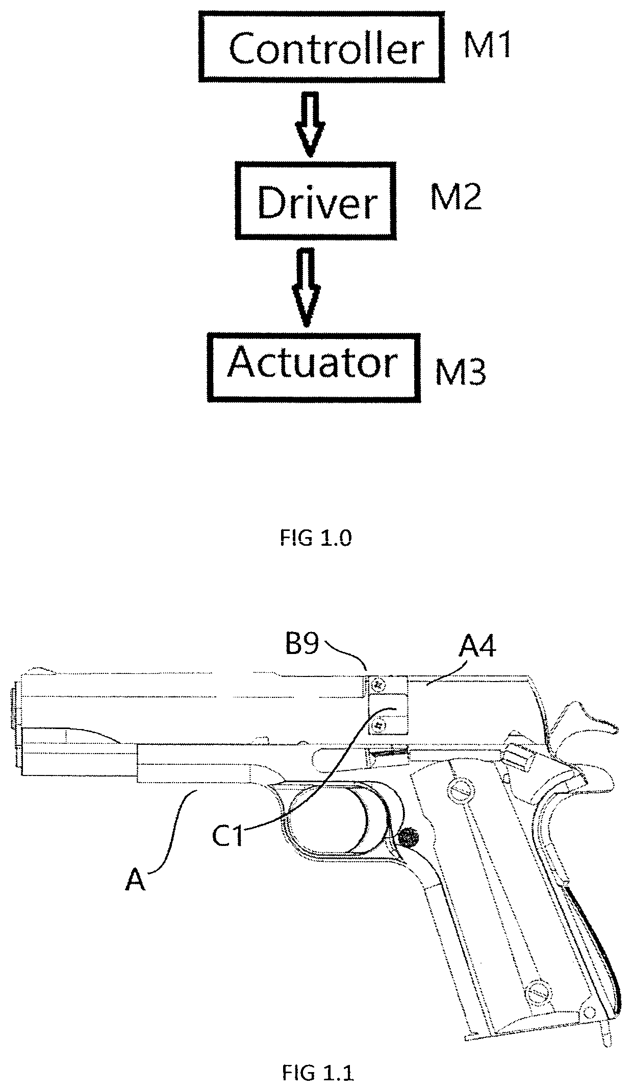
[0265]According to a first preferred embodiment of the present invention, it provides an automatic spring-type lock mechanism C1, which is installed at the middle of the slide A5, which corresponds to the front end B9 of the firing pin A6, as shown in FIGS. 1.1 and 1.2.

[0266]Referring to FIGS. 1.3, 1.4 and 1.5, the lock mechanism C1 includes a lock cover 2, a lock shell 1, a lock tongue actuator 3. The lock shell 1 has a lock core cavity 11, which includes a lock tongue slot 112 and an electromagnet installing slot 113. The lock tongue slot 112 and electromagnet installing slot 113 are in communication with each other via an opening being defined therebetween. A magnet slot 282 and a lock tongue extending hole 28 are located on the lock cover 2, and the magnet slot 282 corresponds to a permanent magnet 30. The lock tongue slot 112 and the electromagnet installing slot 113 on the lock shell 1 correspond to the lock tongue extending hole 28 and the magnet slot 282 on the lock cover 2....

second preferred embodiment

[0275]Referring to FIGS. 2.1 to 2.82, according to a second preferred embodiment of the present invention, it provides an automatic spring-type lock mechanism C2, which is disposed at a position B7 adjacent to the hammer A5 on the slide A4 of the handgun A.

[0276]The automatic spring-type lock mechanism C2 comprises a lock tongue actuator 3a that blocks the space B10 between the firing pin A6 and the hammer A5 with a lock tongue actuator rod 314a as shown in FIGS. 2.71 and 2.72.

[0277]The structure of the lock core and lock shell 1a of the lock mechanism C2 are similar to those of the lock mechanism C1 as shown in FIGS. 1.1 to 1.82.

[0278]The lock mechanism C2 comprises a lock cover 2a, which has two symmetrical side plates: a first lock cover side plate 29a and a second lock cover side plate 29a(a). The distance between the first lock cover side plate 29a and the second lock cover side plate 29a(a) substantially corresponds to or matches with the width of the slide end adjacent to the...

third preferred embodiment

[0285]Referring to FIGS. 3.1 to 3.82, according to a third preferred embodiment of the present invention, it provides an automatic spring-type lock mechanism C3, which is disposed at the grip A7 of a gun A, in which a lock tongue actuator 3b blocks the trigger A2 at the rear side of the trigger A2 with a lock tongue actuator rod 314b. The structure of the lock mechanism C3 is similar to those of the lock mechanisms C1 and C2.

[0286]The automatic spring-type lock mechanism C3 comprises a lock shell 1b, which is box-shaped. The lock shell 1b includes a lock core cavity 11b and a lock cover frustum 21b(a). The lock core cavity 11b includes a lock tongue slot 112b and an electromagnet installing slot 113b. The lock cover 2b has a lock tongue extending hole 28b, a lock cover slot 21b. A lock tongue extending hole 28b corresponds to the lock tongue slot 112b on the lock cover 2b, and a lock cover slot 21b corresponds to the lock cover frustum 21b(a).

[0287]The lock tongue actuator rod 314b ...


PUM


Abstract

Safety lock mechanisms (C1-C28) for a portable weapon is disclosed. Such a mechanism includes an actuator (M3), and locking means operable from an unlocked state to a locked state by the actuator (M3) for blocking a firing sequence of said portable weapon. The blocking of the firing sequence is carried out at a trigger, a trigger lever, a hammer, or a firing pin of the portable weapon. The actuator (M3) may be a push-pull solenoid or servo motor.

Description

CROSS-REFERENCE TO RELATED APPLICATIONS[0001]N / ASTATEMENT REGARDING FEDERALLY SPONSORED RESEARCH OR DEVELOPMENT[0002]N / ANAMES OF THE PARTIES TO A JOINT RESEARCH AGREEMENT[0003]N / A REFERENCE TO A “SEQUENCE LISTING”[0004]N / ABACKGROUND OF THE INVENTIONField of the Invention[0005]The present invention directs to safety lock mechanisms for portable weapons, including, but not limited to, crossbows and firearms, such as guns, rifles and alike.Description of Related Art[0006]Portable weapons, such as crossbows and firearms, for example, guns (such as handguns, for example, pistols and / or revolvers), rifles and alike, are often used for recreational and / or sporting purposes, self-defense where law allows, and / or carried by authorized personals, such as police, military, etc. However, safety issues related thereto are always concerns for the public. Many of portable weapons used today shares substantially similar firing sequence from pulling of a trigger to a firing pin striking a bullet or ...

Claims


Application Information

Patent Timeline
Patent Type & Authority Applications(United States)
IPC IPC(8): F41A17/06
CPCF41A17/06F41A17/74F41A17/46F41A17/64F41A17/54
Inventor SONG, JIUHONGLIU, XINTING
Owner SONG JIUHONG
Learn More