
Heavy Load Lifting System

a lifting system and heavy-duty technology, applied in the direction of lifting devices, lifting equipment safety devices, cranes, etc., can solve the problems of increasing manpower and greater safety measures, affecting the safety of users, so as to achieve efficient and safe manner, without risking the safety of operators

Active Publication Date: 2022-05-12
TETREAU NICHOLAS J
View PDF11 Cites 2 Cited by
  • Summary
  • Abstract
  • Description
  • Claims
  • Application Information

AI Technical Summary

Benefits of technology

The present invention is a heavy load lifting system that can safely and efficiently remove large and heavy components of a vehicle without risking the operator's safety or causing damage to the components. The system includes a frame mounted on a wheeled base and a telescopic boom for lifting the components. It also has various features that enable the operator to tilt, move, and rotate the components in a safe manner. Additionally, it can be used with different shapes and sizes of vehicle components. Overall, the invention provides a safe and efficient solution for removing large and heavy components of a vehicle.

Problems solved by technology

However, the lifting equipment and handling / repair stands currently available can be uncomfortable and sometimes unsafe to use by a single person, which results in more manpower and greater safety measures to be employed.
However, several drawbacks are associated with this prior art.
For example, these tools are specifically designed to remove the pick-up truck box, which means the lack versatility if the user wants to employ the prior art to work on other equipment such as the hood of the truck.
Moreover, the prior art does not include any safety features to protect the operator from injury, which makes the prior art unsafe to use by a single person.

Method used


Image

  • Heavy Load Lifting System
  • Heavy Load Lifting System
  • Heavy Load Lifting System

Examples


Embodiment Construction

[0023]The foregoing and other objects and advantages will appear from the description to follow. It is to be understood, however, that the present invention may be embodied in various forms. These embodiments will be described in sufficient detail to enable those skilled in the art to practice the invention, and it is to be understood that other embodiments may be utilized and that structural changes may be made without departing from the scope of the invention. The following detailed description is, therefore, not to be taken in a limiting sense.

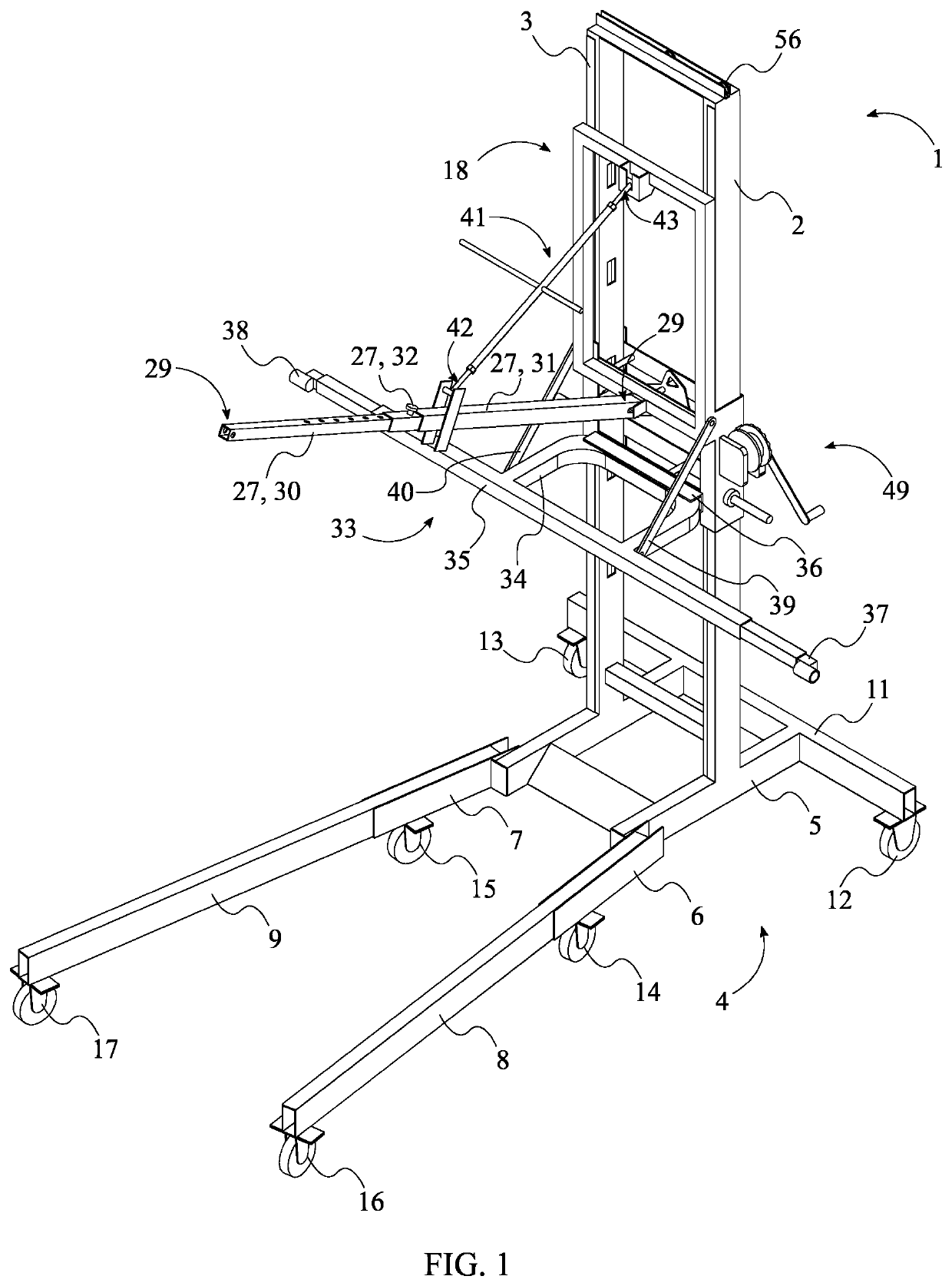
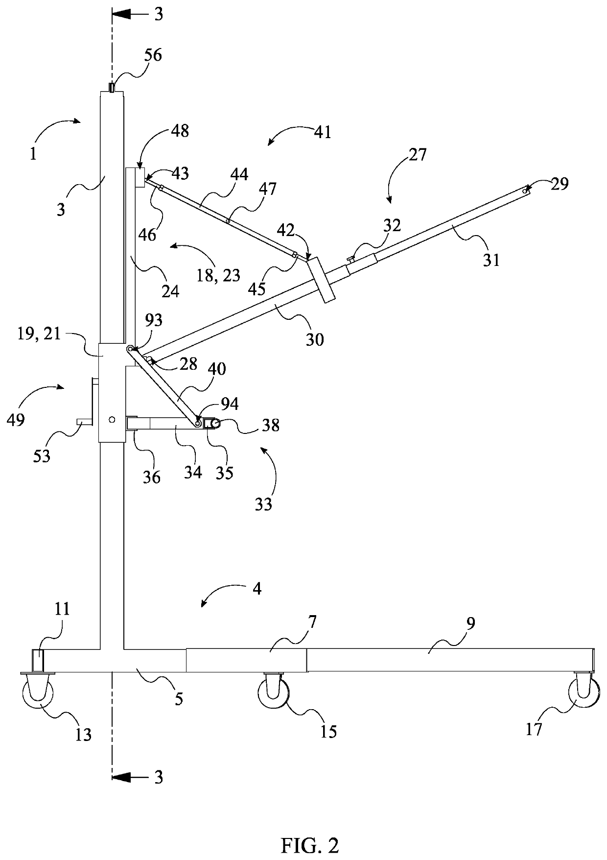
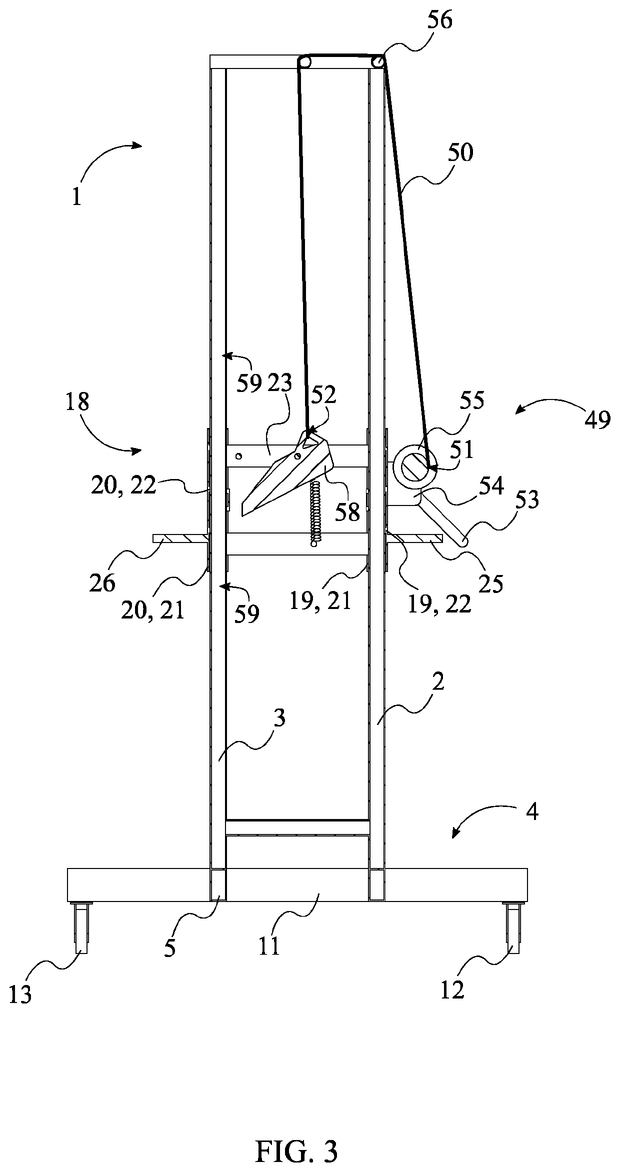
[0024]The present invention is a heavy load lifting system that enables a single repairman to safely lift and mount heavy and / or large vehicle components for repair or maintenance. As can be seen in FIGS. 1, 7, and 8, the present invention may comprise an elongated frame 1, a wheeled base 4, a height-adjustment carriage 18, a telescopic boom 27, a pivot support assembly 33, a tilt-adjustment mechanism 41, and a winch mechanism 49. The elong...


PUM


Abstract

A heavy load lifting system is a system that enables a repairman to safely lift and mount different vehicle components for maintenance or repair. The system may include an elongated frame, a wheeled base, a height-adjustment carriage, a telescopic boom, a pivot support assembly, a tilt-adjustment mechanism, and a winch mechanism. The elongated frame enables the height-adjustment carriage to be raised so that the vehicle component can be removed from the vehicle. The wheeled base enables the system to be moved around. The height-adjustment carriage enables the operator to elevate or lower the telescopic boom. The telescopic boom enables the vehicle component to be removed safely. The pivot support assembly provides additional support to the vehicle component being removed. The tilt-adjustment mechanism enables the telescopic boom to position the removed vehicle component at the desired orientation. The winch mechanism enables the height-adjustment carriage to be moved along the elongated frame.

Description

[0001]The current application claims a priority to the U.S. provisional patent application Ser. No. 63 / 112,531 filed on Nov. 11, 2020.FIELD OF THE INVENTION[0002]The present invention relates generally to lifting equipment and body shop equipment. More specifically, the present invention is a system that enables easy coupling and removal of heavy and / or large components of a vehicle, such as a truck bed or the hood of a truck, by a single person.BACKGROUND OF THE INVENTION[0003]Lifting equipment and handling / repair stands are essential tools for original equipment and automobile manufacturers as well as independent mechanics active in the repair of automobiles and industrial equipment. Many of these tools are used to provide access to the equipment in need of repair or maintenance. During the repair or maintenance process, the piece of equipment, such as an automotive engine or transmission, is lifted in place and fastened to an equipment mount so that the repairman can have full ac...

Claims


Application Information

Patent Timeline
Patent Type & Authority Applications(United States)
IPC IPC(8): B66F7/26B66F7/28
CPCB66F7/26B66F17/00B66F7/28B66C23/48
Inventor TETREAU, NICHOLAS J.
Owner TETREAU NICHOLAS J
Learn More