
Wireless power system, wireless power transmitting apparatus and method for controlling wireless power transmitting apparatus

a wireless power transmission and wireless power technology, applied in the direction of user-computer interaction input/output, capacitors, etc., can solve the problems of inability to control the wireless power to be transmitted, and the conventional wireless power transmission apparatus cannot operate all the plurality of wireless devices, so as to achieve efficient power control, efficiently use, and efficiently manage the operating time of the wireless device.

Pending Publication Date: 2022-05-05
SAMSUNG ELECTRONICS CO LTD
View PDF5 Cites 0 Cited by
  • Summary
  • Abstract
  • Description
  • Claims
  • Application Information

AI Technical Summary

Benefits of technology

The wireless power system in this patent allows for efficient use of power by adjusting the operating power of wireless devices based on their weight and current load. This means that even if multiple devices require more power than the wireless power transmitting apparatus can provide, the system can still use them simultaneously or sequentially. The method also allows for the adjustment of sequential control or simultaneous control, guiding the user's selection. Overall, this wireless power system provides better power control and management for its users.

Problems solved by technology

On the other hand, the conventional wireless power transmitting apparatus can only transmit wireless power having a predetermined magnitude to a wireless device and cannot control the wireless power to be transmitted.
Accordingly, when power required by a plurality of wireless devices exceeds maximum power that can be supplied by the conventional wireless power transmitting apparatus, the conventional wireless power transmitting apparatus cannot operate all of the plurality of wireless devices.

Method used


Image

  • Wireless power system, wireless power transmitting apparatus and method for controlling wireless power transmitting apparatus
  • Wireless power system, wireless power transmitting apparatus and method for controlling wireless power transmitting apparatus
  • Wireless power system, wireless power transmitting apparatus and method for controlling wireless power transmitting apparatus

Examples


Embodiment Construction

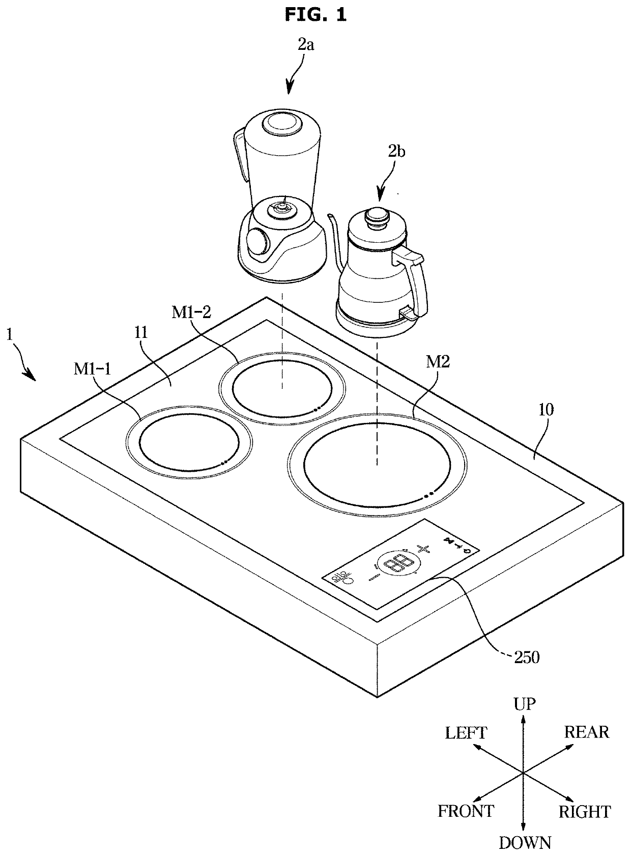
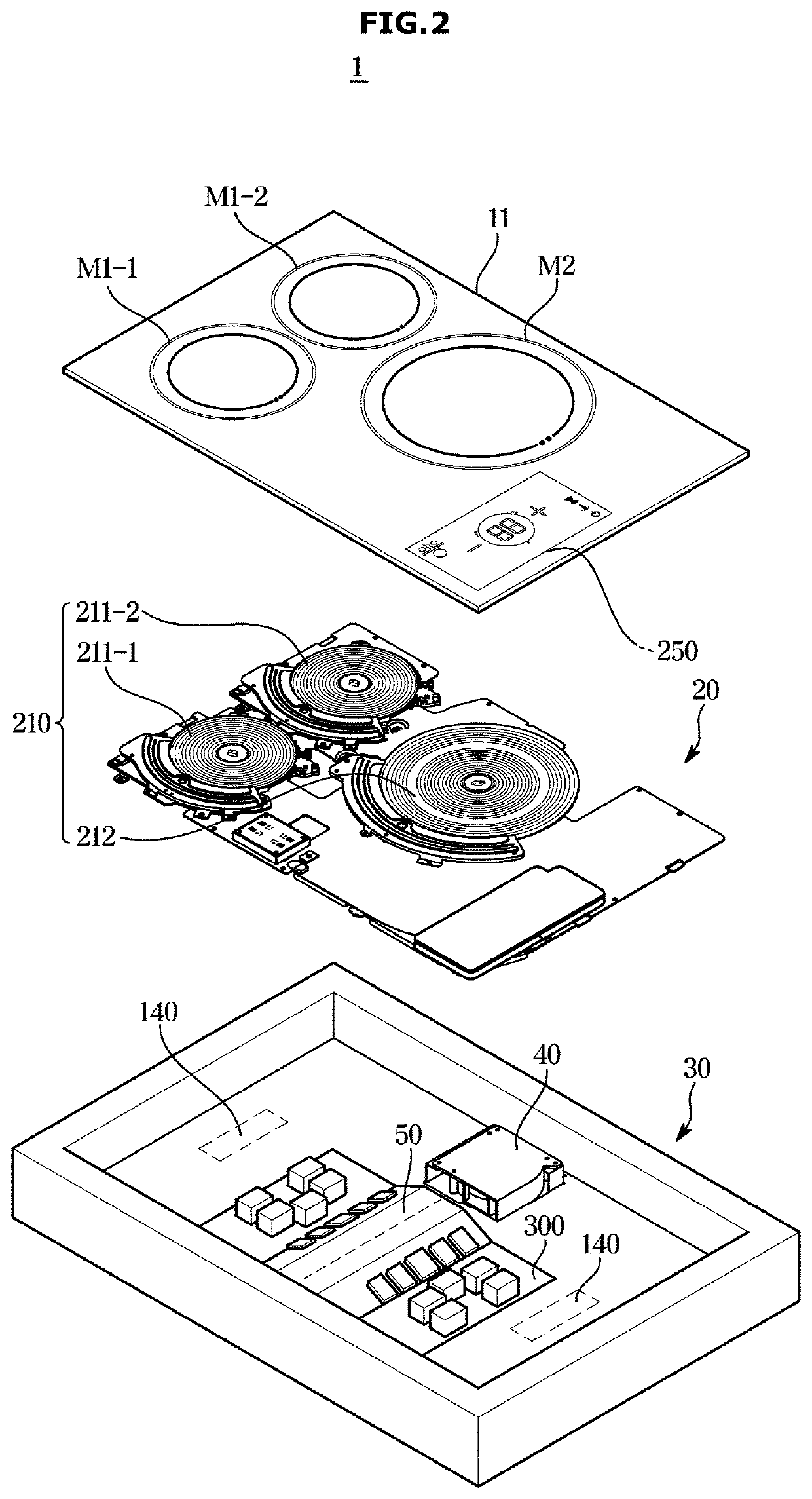
[0046]FIGS. 1 through 12, discussed below, and the various embodiments used to describe the principles of the present disclosure in this patent document are by way of illustration only and should not be construed in any way to limit the scope of the disclosure. Those skilled in the art will understand that the principles of the present disclosure may be implemented in any suitably arranged system or device.

[0047]Like reference numerals refer to like elements throughout the specification. The present specification does not describe all elements of embodiments, and common knowledge in the technical field to which the present invention pertains or the same descriptions of the embodiments will be omitted. The term “unit,”“module,”“member,” or “block” used herein may be implemented using hardware or software. According to the embodiments, one component may be implemented as a plurality of “units,”“modules,”“members,” or “blocks,” or one “unit,”“module,”“member,” or “block” may include a ...


PUM


Abstract

A provided wireless power system includes a plurality of wireless devices, and a wireless power transmitting apparatus including a plurality of transmitting coils, which transmit wireless power to the plurality of wireless devices, and a control panel, wherein the wireless power transmitting apparatus displays, on the control panel, a guide screen related to a selection of simultaneous control or sequential control of the plurality of wireless devices based on the sum of required powers of the plurality of wireless devices in relation to a preset maximum power.

Description

CROSS-REFERENCE TO RELATED APPLICATIONS[0001]This application is a continuation of International Patent Application No. PCT / KR2021 / 015314 filed on Oct. 28, 2021, which claims priority to Korean Patent Application No. 10-2020-0146146 filed on Nov. 4, 2020, the disclosures of which are herein incorporated by reference in their entirety.BACKGROUND1. Field[0002]The disclosed invention relates to a wireless power system which is capable of supplying wireless power to a plurality of wireless devices, a wireless power transmitting apparatus, and a method of controlling the wireless power transmitting apparatus.2. Description of Related Art[0003]Recently, technologies for supplying wireless power have been developed and applied to many electronic devices. Electronic devices, to which wireless power transmission technologies are applied, may wirelessly receive power without requiring a direct connection to a charging connector. For example, technologies have been developed to supply wireless...

Claims


Application Information

Patent Timeline
Patent Type & Authority Applications(United States)
IPC IPC(8): H02J50/80H02J50/40H02J50/12
CPCH02J50/80H02J50/12H02J50/402H02J50/10G06F3/01H01F38/14H02J50/00H02J50/40H02J50/90H04B5/00H02J7/02H02J7/0047H02J50/005Y10S320/18H04B5/79
Inventor KANG, MIJOKIM, MUKYONGKIM, SUNJINJEONG, SANGJINKIM, KWANGYOUNCHANG, KYUNGAH
Owner SAMSUNG ELECTRONICS CO LTD
Learn More