Additive manufacture

Pending Publication Date: 2022-05-05
RENISHAW PLC
View PDF0 Cites 0 Cited by
  • Summary
  • Abstract
  • Description
  • Claims
  • Application Information

AI Technical Summary

Benefits of technology

The invention is about usingfriable, sintered supports in the manufacturing process of components. These supports can be positioned much more flexibly and can be removed without causing any damage to the final component. The method also involves controlling the energy beam to melt selected areas of the powder and solidify them before continuing the process. This can reduce the need for anchor type supports and avoid thermal stresses. Overall, the use of these supports can improve the manufacturing process and make it more efficient.

Problems solved by technology

However, one disadvantage of full-melt processes is that residual stresses are produced in the final component.
Such residual stresses may be such that the final part will distort or crack.
The removal of supports is time consuming and can typically be a manual operation which adds cost and skilled labour to the component manufacture.
Further, when a component is being manufactured to very strict geometrical tolerances the removal of supports can cause difficulty and effect the final surface finish of the component, for example burrs or blemishes may need addressing where supports were attached to the component.

Method used


Image

  • Additive manufacture
  • Additive manufacture
  • Additive manufacture

Examples


Embodiment Construction

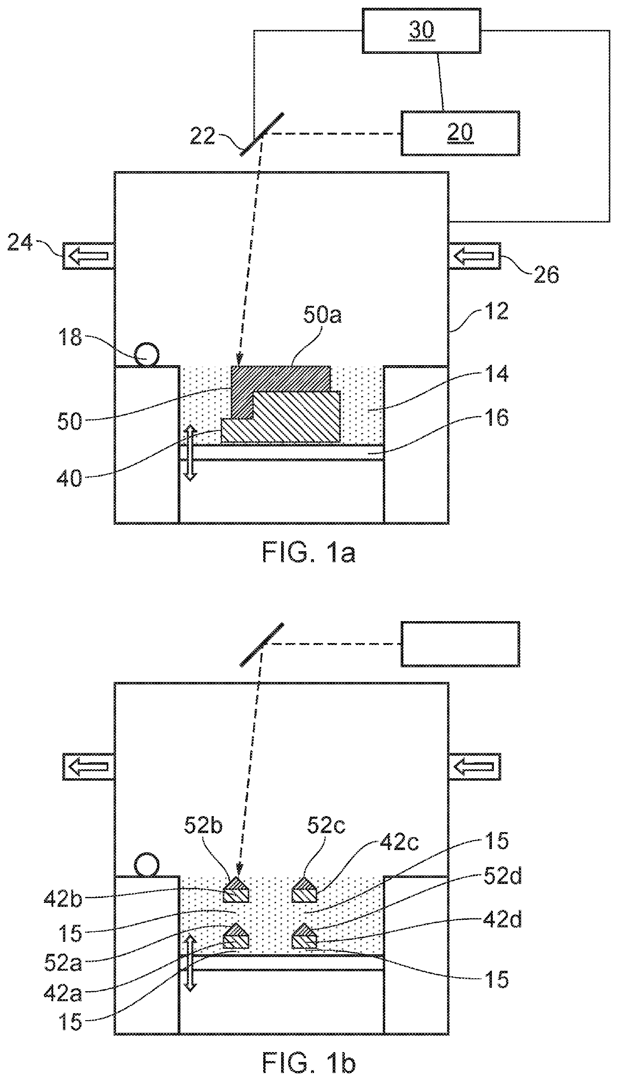
[0058]It may be appreciated that references herein to vertical or horizontal are with reference to the axis of the additive manufacture process. In particular, as powder bed fusion is a layer by layer process the horizontal axis corresponds to the plane of the layers (which is in turn defined by the powder bed and support). The corresponding alignment of a component being manufactured is selected during optimisation of the process and is not therefore limited to any specific direction. Any other references to directions such as above / below or upward / downward are likewise non-limiting with respect to the component per se and should be understood to generally refer to orientation during the additive manufacturing process.

[0059]A metallic powder bed laser fusion additive manufacture apparatus 10 for use in embodiments of the present invention is shown in FIG. 1a. The apparatus may for example be a commercially available apparatus (possibly with some modification to enable embodiments o...


PUM

PropertyMeasurementUnit
Temperatureaaaaaaaaaa
Densityaaaaaaaaaa
Areaaaaaaaaaaa

Abstract

A method of powder bed fusion additive manufacture includes forming a component in a powder bed in a layer-by-layer process. The method may include sintering, without melting, selected regions of powder with an energy beam to form at least one support adjacent to the component; and melting further selected regions of the powder bed with an energy beam to form a component by layer-by-layer melting of material. The method may include directing an energy beam at selected regions of powder to form a friable support, the friable support including bonded powder which act as a solid and provide compressive support; and melting further regions of the powder bed with an energy beam to form a component by layer-by-layer melting of material.

Description

FIELD OF INVENTION[0001]The present invention relates to powder bed fusion additive manufacture.BACKGROUND[0002]Additive manufacturing methods (which in some cases may be referred to as “3D printing”) typically form three-dimensional articles by building up material in a layer-by-layer manner. Additive manufacture has several benefits over traditional manufacturing techniques, for example: additive manufacture has very few limitations on component geometry; additive manufacturing may reduce material waste (as even complex geometries can be produced at or near to their final net-shape); and additive manufacture does not require dedicated tooling so can enable flexible manufacture of small batches or individually tailored products.[0003]One specific type of additive manufacture is powder bed fusion, which is particularly applicable to high strength materials such as metal alloys. In powder bed fusion a thin layer of powder is provided on a base and is selectively exposed to an energy ...

Claims


Application Information

Patent Timeline
IPC IPC(8): B22F10/28B33Y10/00B33Y30/00B23K26/06B23K26/03B23K26/342
CPCB22F10/28B33Y10/00B33Y30/00B22F10/85B23K26/034B23K26/342B23K26/0626Y02P10/25B22F10/36B22F12/17B22F10/37B22F12/90B22F10/47B22F12/44B22F12/45B33Y50/02
Inventor MCFARLAND, GEOFFREYWESCOTT, ANDREW DAVID
Owner RENISHAW PLC
Why Eureka
Try Eureka