Modular docking system for electrosurgical equipment

a technology of electrosurgical equipment and module, applied in the field of surgical systems, can solve the problems of affecting the introduction of new technology, affecting the operation room, and occupying valuable space by new modules or devices, and achieve the effect of reducing footprint and less cabling

Pending Publication Date: 2022-05-05
CONMED CORP
View PDF0 Cites 0 Cited by
  • Summary
  • Abstract
  • Description
  • Claims
  • Application Information

AI Technical Summary

Benefits of technology

[0005]The present invention provides for a reduced footprint and less cabling in an operating room using a docking system having a first docking interface comprising a recess in a first housing associated with a first electrosurgical device, wherein the recess includes a first set of electrical contacts extending thereacross and a second docking interface comprising a raised portion in a second housing associated with a second electrosurgical device, wherein the raised portion includes a first set of electrical contacts extending thereacross. The recess is configured to receive the raised portion therein when the first docking interface and second docking interface are positioned together so that the first set of electrical contacts are coupled to and in electrical communication with the second set of electrical contacts. The first set of electrical contacts are arranged linearly across the recess and the second set of electrical contacts are arranged linearly across the raised portion. The first electrosurgical device may be a smoke evacuator, while the second electrosurgical device may be an electrosurgical unit. The first set of electrical contacts are positioned on an upper surface the smoke evacuator, and the second set of electrical contacts are positioned on a lower surface of the electrosurgical unit so that the devices are interconnected by stacking the electrosurgical unit on the smoke evacuator. The first set of electrical contacts and the second set of electrical contacts each comprise a pair of ground contacts, a pair of power contacts, and a series of communication contacts so that the smoke evacuator can powered by the electrosurgical unit and the smoke evacuator will be in communication with the electrosurgical unit via the first docking interface and the second docking interface. The first docking interface extends transversely across an upper surface of the housing of the smoke evacuator and the second docking interface extends transversely across a lower surface of the housing of the electrosurgical unit. The upper surface of the housing of the smoke evacuator may include a third docking interface comprising a recess that corresponds to a fourth docking interface comprising a raised portion on the upper surface of the smoke evacuator that can be received by the recess of the third docking interface. The first docking interface may thus extend across a front portion of the smoke evacuator, the third docking interface may extend across a rear portion of the smoke evacuator, the second docking interface may extend across a front portion of the electrosurgical unit, and the fourth docking interface may extend across a rear portion of the electrosurgical unit.

Problems solved by technology

While the addition of innovative and novel technology is needed and desired within the operating room, logistical issues, such as space and power constraints, often arise and can inhibit the introduction of new technology.
For example, new modules or devices can take up valuable space within the operating room.
In addition, operating rooms may also have a limited number of power outlets in a limited number of locations, resulting in a user having to place devices in non-ideal locations, which can become a safety hazard.

Method used


Image

  • Modular docking system for electrosurgical equipment
  • Modular docking system for electrosurgical equipment
  • Modular docking system for electrosurgical equipment

Examples


Embodiment Construction

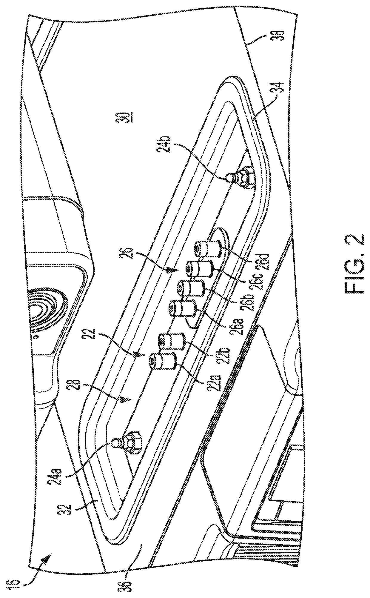
[0012]Referring to the figures, wherein like numeral refer to like parts throughout, there is seen in FIG. 1 an electrosurgical system 10 having two or more interconnected modules, shown as an electrosurgical unit 12 and a smoke evacuator 14. Electrosurgical unit 12 and smoke evacuator 14 are interconnected using an upwardly facing docking interface 16 of smoke evacuator 14 that mates with a corresponding downwardly docking interface 20 of electrosurgical unit 12.

[0013]Referring to FIG. 2, docking interface 16 includes a series of power connectors 22, ground studs 24, and communication ports 26, shown as male style connectors positioned within a recessed portion 28 of the housing 30 of smoke evacuator 14. More specifically, docking interface 16 comprises a pair of ground studs 24a and 24b positioned at opposing ends 32 and 34 of recessed portion 28. Recessed portion 28 extends transversely across a forward portion 36 of the upper surface 38 of housing 30. Ground studs 24a and 24b ma...


PUM


Abstract

A docking system for electrosurgical equipment where a first docking interface is a recess in the housing of a smoke evacuator and a second docking interface is a raised portion of an electrosurgical unit. The first and second docking interfaces have corresponding ground, power, and communication contacts, so that the two devices can be physically and electrically interconnected by mating the first docking interface with the second docking interface. The first docking interface is on the top of the smoke evacuator and the second docking interface is on the bottom of the electrosurgical unit so that the devices may be stacked and interconnected using a minimum amount of space without the need for cabling.

Description

CROSS-REFERENCE TO RELATED APPLICATIONS[0001]The present application claims priority to U.S. Provisional No. 62 / 810,486 filed on Feb. 26, 2019.BACKGROUND OF THE INVENTION1. Field of the Invention[0002]The present invention relates to surgical systems and, more specifically, to a system for interconnecting electrosurgical systems to reduce complexity and optimize space.2. Description of the Related Art[0003]While the addition of innovative and novel technology is needed and desired within the operating room, logistical issues, such as space and power constraints, often arise and can inhibit the introduction of new technology. For example, new modules or devices can take up valuable space within the operating room. In addition, operating rooms may also have a limited number of power outlets in a limited number of locations, resulting in a user having to place devices in non-ideal locations, which can become a safety hazard.[0004]As an example, smoke evacuators used in combination with...

Claims


Application Information

Patent Timeline
Patent Type & Authority Applications(United States)
IPC IPC(8): A61B18/12
CPCA61B18/1206A61B2560/0443A61B2018/00178A61B2560/0214A61B2218/008A61B2560/0456
Inventor FRAME, DANCOOK, JOHN
Owner CONMED CORP
Why Eureka
Try Eureka