Optical system and lighting device

a technology of optical systems and lighting devices, applied in the field of optical systems, can solve the problems of further reducing the overall size unsatisfactory light mixing properties of such optical systems, etc., and achieve the effect of improving the efficiency of light ray mixing and improving the optical efficiency of the optical system

Active Publication Date: 2022-04-21
SIGNIFY HLDG BV
View PDF0 Cites 0 Cited by
  • Summary
  • Abstract
  • Description
  • Claims
  • Application Information

AI Technical Summary

Benefits of technology

The present invention provides a solution for improving the mixing of light rays in an optical system. This is achieved by using a lenslet plate carrying lenslet arrays on opposing surfaces, which acts as a Kohler integrator. The lenslet plate is designed to mix light rays that are incident on the plate's surface at a certain angle. The first surface of the lenslet plate contacts with its first array of lenslets, while the second surface contacts with its second array of lenslets. The lenslets in each array are arranged in a Fermat spiral pattern to achieve good uniformity of the luminous output of the optical system. The elongated body of the light mixing rod may be made of an optically transmissive material or a hollow body with inner surfaces carrying facets or ripples to improve the efficiency of light mixing. The light mixing rod has an elongate body with an appropriate aspect ratio to effectively mix all light rays. The optical system may also include a collimator to produce a narrow beam.

Problems solved by technology

However, where the optical system comprises a large diversity of luminous inputs from the solid state lighting elements in terms of spectral composition, it has been found that the light mixing properties of such an optical system are unsatisfactory.
However, there exists a need to further reduce the overall size of such an optical system.

Method used


Image

  • Optical system and lighting device
  • Optical system and lighting device
  • Optical system and lighting device

Examples


Embodiment Construction

[0034]It should be understood that the Figures are merely schematic and are not drawn to scale. It should also be understood that the same reference numerals are used throughout the Figures to indicate the same or similar parts.

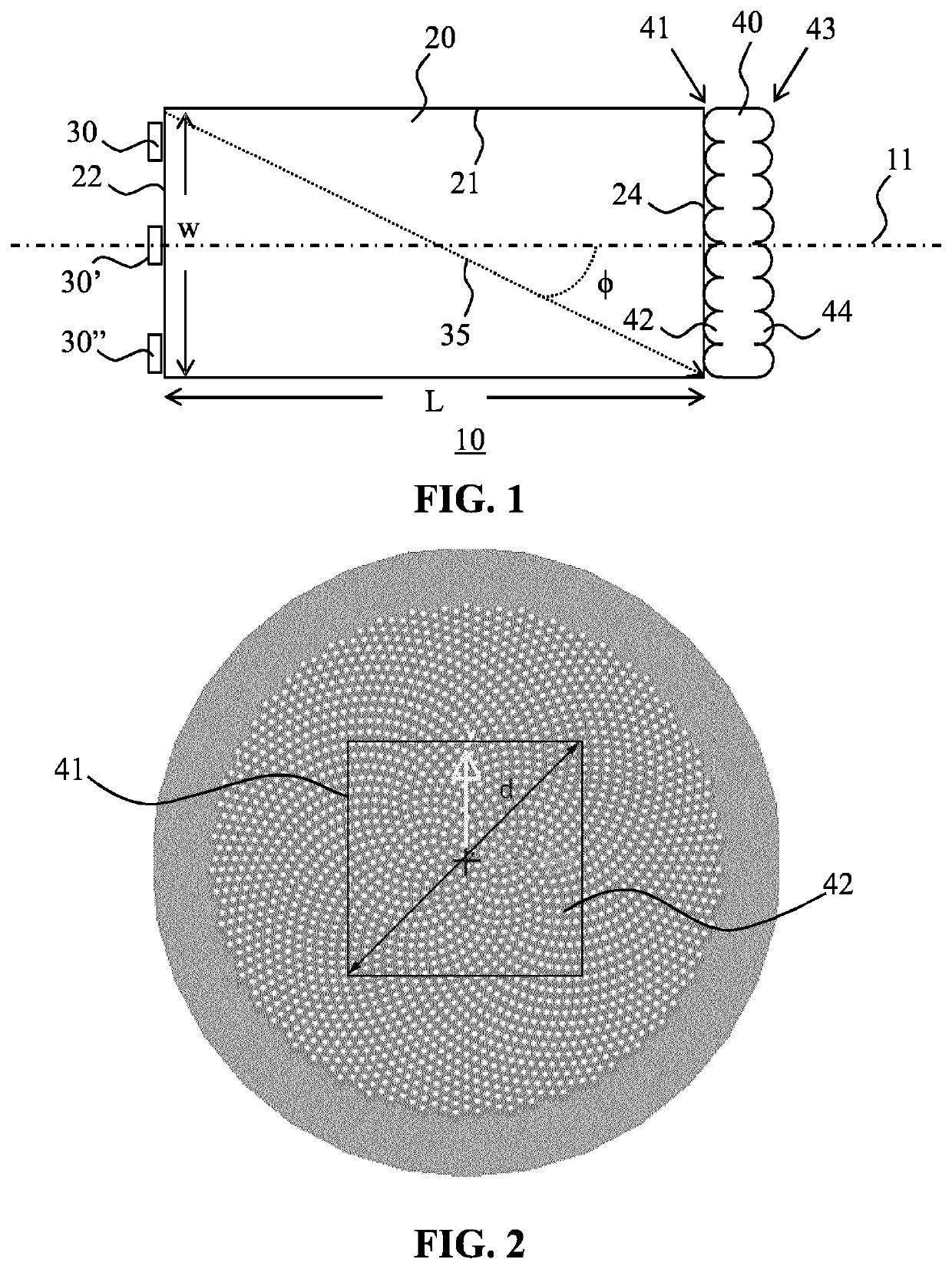
[0035]FIG. 1 schematically depicts a cross-sectional view of an optical system 10 according to an embodiment of the present invention. The optical system 10 comprises a light mixing rod 20 having an elongated body extending between a light entry window 22 having a maximum cross-section w and a light exit window 24. In the context of the present application, where reference is made to the maximum cross-section of a surface, this is meant to define the largest linear distance across such a surface. For example, for a circular surface this is the diameter of the circle, for a rectangular surface this is the major diagonal across such a surface and so on. Moreover, where reference is made to a window, this is to be understood as any feature that allows light to p...


PUM

PropertyMeasurementUnit
lengthaaaaaaaaaa
acceptance angleaaaaaaaaaa
refractive indexaaaaaaaaaa

Abstract

An optical system (10) is disclosed comprising a light mixing rod (20) having an elongate body extending between a light entry window (22) and an opposing light exit window (24), a plurality of solid state lighting elements (30, 30′, 30″) arranged to couple their respective luminous outputs into the light mixing rod (20) through said light entry window (22), said respective luminous outputs including luminous outputs having different spectral compositions, respectively, and a lenslet plate (40) having an acceptance angle (ψ,ψ′) and comprising a first surface (41) comprising a first array of lenslets (42) and a second surface (43) opposing the first surface (41) comprising a second array of lenslets (44), each lenslet of the first array (42) being aligned with a corresponding lenslet of the second array (44), wherein the light mixing rod (20) has an aspect ratio such that some light rays (35) produced by the solid state lighting elements (30, 30′, 30″) are directly incident on said first surface (41), said directly incident light rays (35) having a maximum angle of incidence (Φ) on said first surface (41) not exceeding said acceptance angle. Also disclosed is a lighting device comprising such an optical system (10).

Description

FIELD OF THE INVENTION[0001]The present invention relates to an optical system comprising a light mixing rod having an elongate body extending between a light entry window and an opposing light exit window and a plurality of solid state lighting elements arranged to couple their respective luminous outputs into the light mixing rod through said light entry window, said respective luminous outputs including luminous outputs having different spectral compositions respectively.[0002]The present invention further relates to a lighting device comprising such an optical system.BACKGROUND OF THE INVENTION[0003]Light mixing rods, sometimes also referred to as light pipes, are optically transmissive bodies that can be used to mix incident light of different spectral compositions, e.g. light of different colours, such that the output of such a light mixing rod has an improved spectral homogeneity compared to the light that is coupled into the light mixing rod. For example, a light mixing rod ...

Claims


Application Information

Patent Timeline
Patent Type & Authority Applications(United States)
IPC IPC(8): G02B3/00F21V5/00F21V7/00
CPCG02B3/0068F21Y2105/10F21V7/0091F21V5/004G02B6/0096G02B19/0028G02B19/0066F21Y2115/10G02B27/0994F21Y2113/13
Inventor BOONEKAMP, ERIK PAUL
Owner SIGNIFY HLDG BV
Why Eureka
Try Eureka