
Power-driven shoe device wheel configuration with combined translational and rotational hinge mechanism and integrated gear-bushing assembly

a technology of power-driven shoe device and hinge mechanism, which is applied in the direction of skateboards, roller skates, sport apparatus, etc., can solve the problems of user inconvenience, increased physical exertion, and commuting public's relative long and time-consuming final walking distance,

Pending Publication Date: 2022-04-21
NIMBUS ROBOTICS INC
View PDF19 Cites 2 Cited by
  • Summary
  • Abstract
  • Description
  • Claims
  • Application Information

AI Technical Summary

Benefits of technology

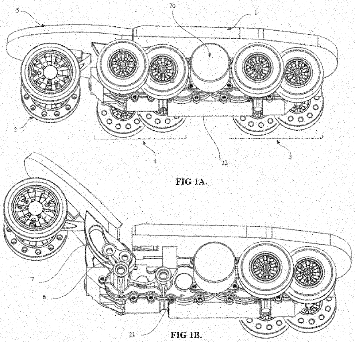
The present invention provides a power-driven shoe that has a unique design and can be used for both walking and running. The shoe has wheels that rotate and are in driving connection with a motor. The shoe also has hinges that allow the shoe to move and absorb shocks. Additionally, the shoe has a battery and circuitry components for powering the shoe. The shoe can also be secured to a user's foot using a magnetic buckle. The technical effects of the invention include improved stability, reduced fatigue, and improved performance.

Problems solved by technology

With increasing urban populations and concerns of disease transmission on shared commuting methods, such as public transportation, the last kilometer problem, that is, a relatively long and time-consuming final walking distance remains an issue for the commuting public.
The current market solutions of electric roller skates present a problem, namely a non-bending sole, or platform, whereby the user cannot keep a normal walking posture and gait cycle, from the heels touching the ground to the forefoot parts pedaling the ground.
Abnormal posture and gait cycle creates discomfort and causes extra physical exertion.
These issues are compounded by the increasing complexity of urban roads and sidewalks where commuters must enter and exit sidewalks while avoiding obstacles such as holes, grates, or puddles.
This complexity makes the user unable to walk normally in electric roller skates, thereby greatly reducing the practicality of the current technology.
Current wheel configurations that are under the users sole present challenges when going over obstacles and present dangerous scenarios of sudden deceleration or unexpected stopping.
The bulk of the electronic equipment required to drive and a transportation device reduces the applicability and ergonomic use due to increased weight and width.
As such, the skates may impact each other or obstacles.
Furthermore, with the recent appearance of multi-body electric roller skates, the hinge point creates undesirable compression of the user's foot and allows for a source of instability at certain angles of the foot relative to the ground plane, whereby the number of wheels in contact with the ground is suddenly reduced.

Method used


Image

  • Power-driven shoe device wheel configuration with combined translational and rotational hinge mechanism and integrated gear-bushing assembly
  • Power-driven shoe device wheel configuration with combined translational and rotational hinge mechanism and integrated gear-bushing assembly
  • Power-driven shoe device wheel configuration with combined translational and rotational hinge mechanism and integrated gear-bushing assembly

Examples


Embodiment Construction

[0034]This disclosure is not limited to the particular systems, devices and methods described, as these may vary. The terminology used in the description is for the purpose of describing the particular versions or embodiments only, and is not intended to limit the scope of the disclosure.

[0035]The following terms shall have, for the purposes of this application, the respective meanings set forth below. Unless otherwise defined, all technical and scientific terms used herein have the same meanings as commonly understood by one of ordinary skill in the art. Nothing in this disclosure is to be construed as an admission that the embodiments described in this disclosure are not entitled to antedate such disclosure by virtue of prior invention.

[0036]As used herein, the singular forms “a,”“an,” and “the” include plural references, unless the context clearly dictates otherwise. Thus, for example, reference to a “cell” is a reference to one or more cells and equivalents thereof known to thos...


PUM


Abstract

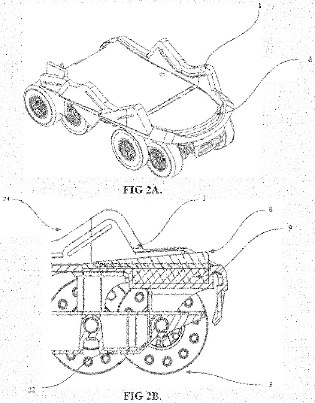
Disclosed is a power-driven shoe. The shoe includes a shoe sole having a plurality of rotatable wheels arranged below the shoe sole in an overlapping fashion. The distance between the rotational axis of the wheels is less than or equal to the diameter of the wheel, such that vertical obstacles can be overcome in both the positive and negative displacement directions for increased ground stability. The shoe sole includes a toe part and a sole part that are connected to each other, via a hinge, in both a rotational and translational configuration, such that at least one front wheel or at least one middle wheel are independently in contact with the ground while maintaining at least one rear wheel in contact with the ground throughout a bi-pedal gait cycle, allowing for comfort during a user's natural range of motion.

Description

CROSS-REFERENCE TO RELATED APPLICATIONS[0001]This application claims priority to and benefit of U.S. Provisional Application Ser. No. 63 / 094,738, filed Oct. 21, 2020, entitled “Power-driven shoe device wheel configuration with combined translational and rotational hinge mechanism and integrated gear-bushing assembly,” which is incorporated herein by reference in its entirety.TECHNICAL FIELD[0002]The present application relates to a power-driven shoe device with a multi-wheel configuration, a wheel design with localized deformation zones, a combined translational and rotational hinge device, a heel cushioning mechanism, an integrated gear-bushing assembly, and a one-piece power module suitable for a variety of uses, including, but not limited to the field of transportation tools.BACKGROUND[0003]With increasing urban populations and concerns of disease transmission on shared commuting methods, such as public transportation, the last kilometer problem, that is, a relatively long and ti...

Claims


Application Information

Patent Timeline
IPC IPC(8): A63C17/12A63C17/04A63C17/20
CPCA63C17/12A63C2203/12A63C17/20A63C17/04A63C2203/22A63C17/0073A63C17/262A63C2203/18A63C17/22B60C7/107
Inventor ZHANG, XUNJIEPLETA, ABRAM
Owner NIMBUS ROBOTICS INC
Learn More