
Power Module for Operating an Electric Vehicle Drive with an Intermediate Circuit Capacitor

a technology of power modules and capacitors, applied in the field of electric vehicles, can solve the problems of affecting inducing high voltage etc., and achieve the effects of reducing the probability and magnitude of voltage peaks, reducing leakage inductance of electrical lines in the power module, and improving the functionality of the power modul

Active Publication Date: 2022-04-14
ZF FRIEDRICHSHAFEN AG
View PDF2 Cites 0 Cited by
  • Summary
  • Abstract
  • Description
  • Claims
  • Application Information

AI Technical Summary

Benefits of technology

The invention aims to protect power semiconductors from voltage peaks during switching on and off to improve the performance of power modules. The contact elements of the current input and circuit-breakers are arranged on the first metal layer of the substrate, which reduces the distance between them. This reduces the leakage inductance of the electrical lines and reduces the probability and magnitude of voltage peaks that may cause circuit-breakers to blow. This results in improved power module functionality, particularly when using WBG semiconductor materials that provide faster switching times.

Problems solved by technology

Nevertheless, the power modules known from the prior art have the disadvantage that the short switching times of the utilized semiconductor materials induce high voltages in these power modules in the presence of leakage inductance prevailing in the power lines of the power module during the switching on and off of the circuit-breakers.
High voltages can cause the circuit-breakers and / or the power semiconductors contained therein to blow and, thereby, become adversely affected.

Method used


Image

  • Power Module for Operating an Electric Vehicle Drive with an Intermediate Circuit Capacitor

Examples


Embodiment Construction

[0021]Reference will now be made to embodiments of the invention, one or more examples of which are shown in the drawings. Each embodiment is provided by way of explanation of the invention, and not as a limitation of the invention. For example, features illustrated or described as part of one embodiment can be combined with another embodiment to yield still another embodiment. It is intended that the present invention include these and other modifications and variations to the embodiments described herein.

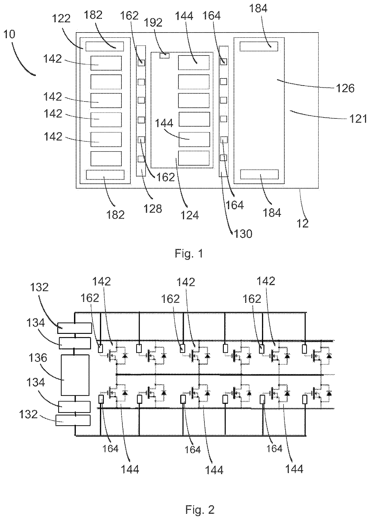
[0022]FIG. 1 shows a schematic of a power module 10 according to one example embodiment. The power module 10 includes a plurality of circuit-breakers 142, 144, which are arranged on a metal layer 122, 124, respectively. The metal layer 122, 124 is part of a substrate 12, which additionally includes an insulating layer 121, on which the metal layer 122, 124, 126 is arranged. The metal layer has a first zone 122, in which a first circuit-breaker group of the circuit-breakers 142 is ...


PUM


Abstract

A power module (10) for operating an electric vehicle drive includes a current input configured for supplying an input current. The current input includes multiple contact elements (182, 184). Multiple circuit-breakers (142, 144) are configured for generating an output current based on the supplied input current. A current output (192) is configured for outputting the output current at a consumer. A substrate (12) includes a metal layer (122-130) and an insulating layer (121) connected to the metal layer (122-130). The multiple circuit-breakers (142, 144) are arranged on the metal layer (122-130). The multiple contact elements (182, 184) are also arranged on the metal layer (122-130) such that the multiple contact elements (182, 184) extend perpendicular to a surface of the substrate (12).

Description

CROSS-REFERENCE TO RELATED APPLICATION[0001]The present application is related and has right of priority to German Patent Application No. 102020212748.4 filed in the German Patent Office on Oct. 8, 2020, which is incorporated by reference in its entirety for all purposes.FIELD OF THE INVENTION[0002]The present invention relates generally to the field of electromobility, in particular of the power modules for operating an electric drive for a vehicle.BACKGROUND[0003]Power modules, in particular integrated power modules, are being used to an increasing extent in motor vehicles. These types of power modules are used, for example, in DC / AC inverters, which are utilized for energizing electric machines, such as electric motors, with a multiphase alternating current. In the process, a direct current generated by a DC energy source, for example, a battery, is converted into a multiphase alternating current. The power modules are based on power semiconductors, in particular transistors such...

Claims


Application Information

Patent Timeline
Patent Type & Authority Applications(United States)
IPC IPC(8): B60L3/04H03K17/56B60L53/20
CPCB60L3/04B60L53/20H03K17/56H03K17/122H03K17/08104H01L25/072B60L3/003B60L15/007B60L2240/529B60L2240/525Y02T10/70Y02T10/7072Y02T90/14H01L2924/13091H01L2924/13055H01L2924/10272H01L2924/1033H01L2924/10253H01L2924/13064H01L2924/19041H01L2924/19043H01L2924/19105H01L2924/30107H01L23/62H01L23/60
Inventor LIU, WEI
Owner ZF FRIEDRICHSHAFEN AG
Learn More