Gimbal Joints for Bleed Air Systems

a technology of bleed air and ducting, which is applied in the direction of adjustment joints, pipe joints, mechanical equipment, etc., can solve the problems of difficult or impossible production of precise designs using other manufacturing techniques, and achieve the effect of adequate resistance to shear forces and flexibility

Pending Publication Date: 2022-03-31
SENIOR IP GMBH
View PDF9 Cites 0 Cited by
  • Summary
  • Abstract
  • Description
  • Claims
  • Application Information

AI Technical Summary

Benefits of technology

This patent describes a new design for a gimbal ring used in a device. The design includes one or more struts that form a shear web. The gimbal ring can be made using traditional methods such as casting or machining, or by additive manufacturing. By forming the gimbal ring with an optimized topology that takes into account its desire to withstand shear force while also being lightweight, the design includes placement of material and omission of material to create gaps that increase its stiffness-to-mass ratio. This results in the gimbal ring being capable of withstanding significant shear forces while also being lightweight.

Problems solved by technology

Some additive manufacturing techniques are capable of producing intricate and precise designs that would be difficult or impossible to produce using other manufacturing techniques.

Method used


Image

  • Gimbal Joints for Bleed Air Systems
  • Gimbal Joints for Bleed Air Systems
  • Gimbal Joints for Bleed Air Systems

Examples


Embodiment Construction

[0079]There will now be described by way of example, several specific modes of the invention as contemplated by the inventors. In the following description, numerous specific details are set forth in order to provide a thorough understanding. It will be apparent however, to one skilled in the art, that the present invention may be practiced without limitation to these specific details. In other instances, well known methods and structures have not been described in detail so as not to unnecessarily obscure the description of the invention.

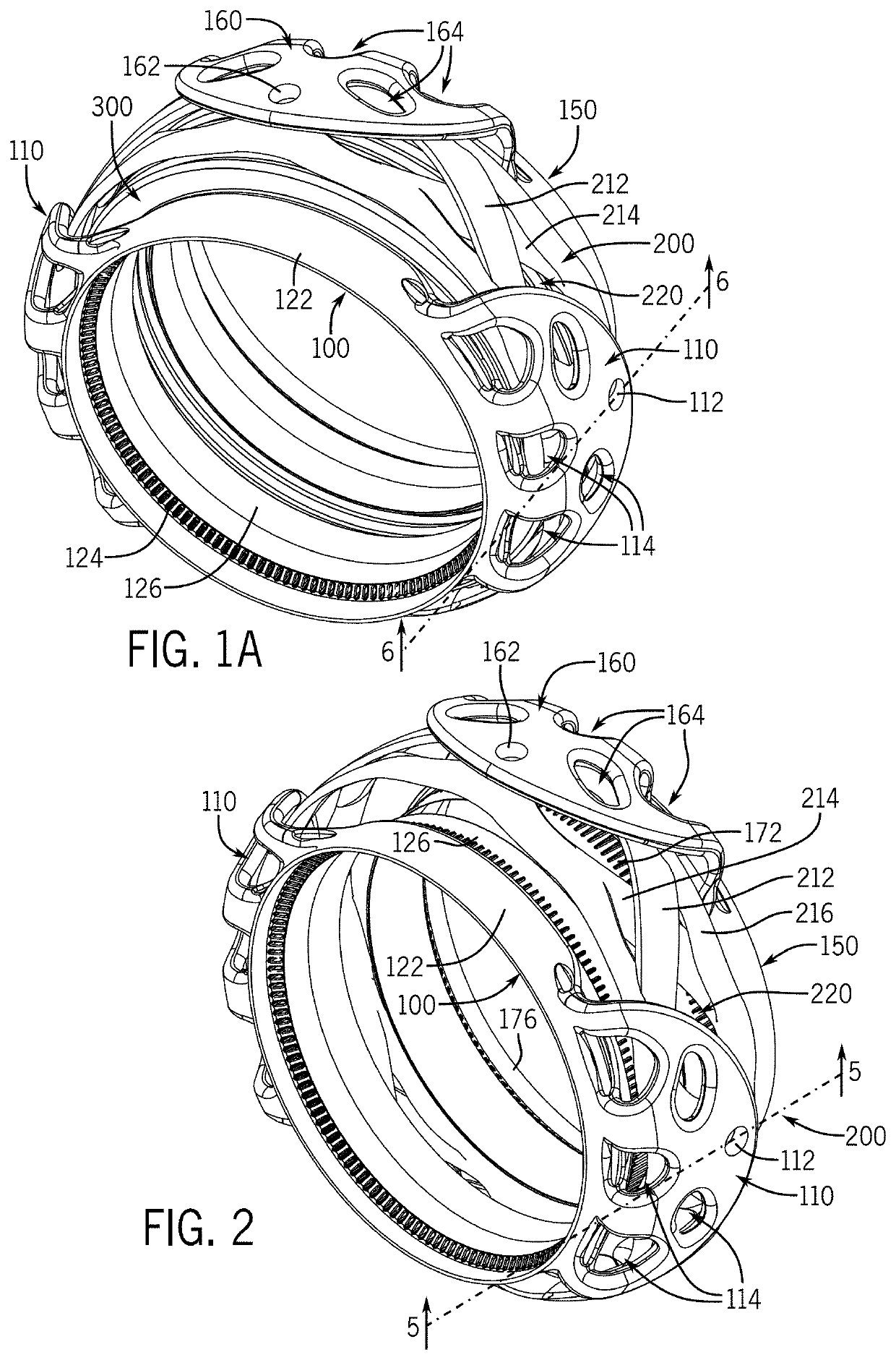
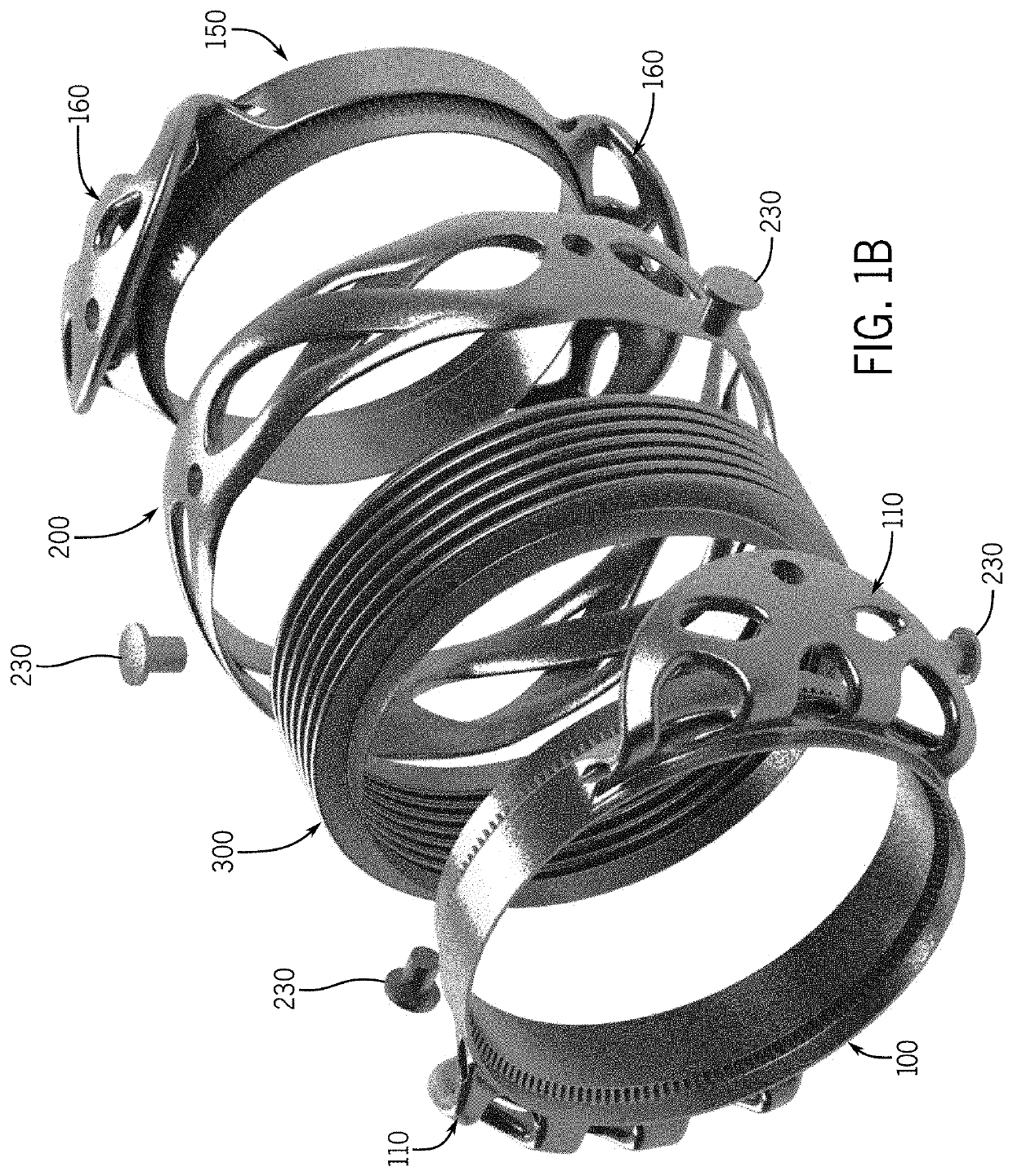
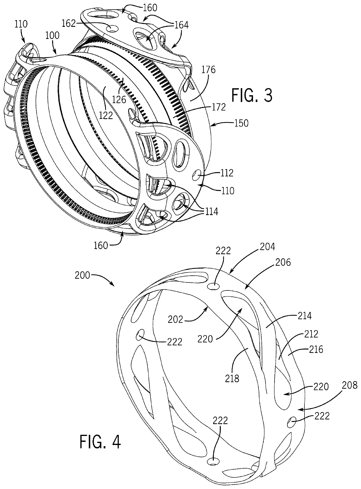
[0080]As described above, it is an objective of the present invention to provide gimbal joint designs and optimization techniques that balance the strength and structural integrity of the gimbal joint with the overall weight of the gimbal joint assembly. The gimbal joints may be geometrically optimized and / or topologically optimized, such that the gimbal joint assembly satisfies a set of design requirements and anticipated loads, while simultaneous...


PUM


Abstract

A sealed joint assembly for transmitting high temperature and high pressure fluid between adjoining ducts in, for example, an aircraft bleed air system, includes a gimbal ring and two annular clevises. Each clevis includes a pair of axially-extending lobes that each includes a bore hole extending therethrough. The bore holes of the clevis lobes may each align with a respective bore hole formed within the gimbal ring, through which a pin may be inserted to couple the clevises to the gimbal ring. The clevises and gimbal ring may be formed using additive manufacturing, and may be optimized to reduce the joint assembly's overall weight, while maintaining or improving its structural integrity. The gimbal ring may include a strut or truss network to enhance structural integrity, and may be comprised of an inner gimbal ring and an outer gimbal ring.

Description

RELATED APPLICATION DATA[0001]This application is a Continuation-in-Part of U.S. patent application Ser. No. 16 / 442,541 entitled “GIMBAL JOINTS FOR BLEED AIR SYSTEMS,” filed Jun. 16, 2019, the contents of which are incorporated herein in their entirety and for all purposes.FIELD OF THE INVENTION[0002]The present invention generally relates to gimbal joints for ducting, and more specifically to sealed gimbal joint assemblies for flexibly connecting ducts that transmit high temperature and high pressure fluids, such as bleed air ducting systems in aircraft or spacecraft, and more particularly to reduced-weight gimbal joint designs that maintain sufficient structural integrity and provide suitable flexibility for high performance aerospace applications.BACKGROUND OF THE INVENTION[0003]Ducting systems are commonly used to convey high pressure, high temperature fluids across sections of a system. Ducting systems are typically constructed from a series of conduits that are fluidly coupled...

Claims


Application Information

Patent Timeline
IPC IPC(8): F16L27/08
CPCF16L27/0857
Inventor THOMPSON, CHRISTOPHERPARKER, MATTHEWPOSSERT, ERIC
Owner SENIOR IP GMBH
Why Eureka
Try Eureka