
Laser welded assembly having a heat affected zone reinforcement and method of making the same

Pending Publication Date: 2022-03-31
GM GLOBAL TECH OPERATIONS LLC +1
View PDF0 Cites 0 Cited by
  • Summary
  • Abstract
  • Description
  • Claims
  • Application Information

AI Technical Summary

Benefits of technology

The patent text discusses the issue of heat-affected zones (HAZ) in narrow laser welds, which can negatively impact the strength and energy absorption of the joint. The HAZ is a non-melted area of metal that has undergone changes in material properties as a result of high temperatures during the laser welding process. The text describes a technical solution to mitigate the negative impact of HAZ on joint strength and performance.

Problems solved by technology

The strength of the laser weld may be adversely affected by the HAZ formed immediately adjacent to the weld seam during the laser welding process.
The HAZ weakens the joint strength and energy absorption of the overlapping portions of the metal panel members since the HAZ is close to the notch root area where stress is concentrated under loading condition.

Method used


Image

  • Laser welded assembly having a heat affected zone reinforcement and method of making the same
  • Laser welded assembly having a heat affected zone reinforcement and method of making the same
  • Laser welded assembly having a heat affected zone reinforcement and method of making the same

Examples


Embodiment Construction

[0041]The following description is merely exemplary in nature and is not intended to limit the present disclosure, application, or uses. The illustrated embodiments are disclosed with reference to the drawings, wherein like numerals indicate like corresponding parts throughout the several drawings. The figures are not necessarily to scale and some features may be exaggerated or minimized to show the details of particular features. The specific structural and functional details disclosed are not intended to be interpreted as limiting, but as a representative basis for teaching one skilled in the art as to how to practice the disclosed concepts.

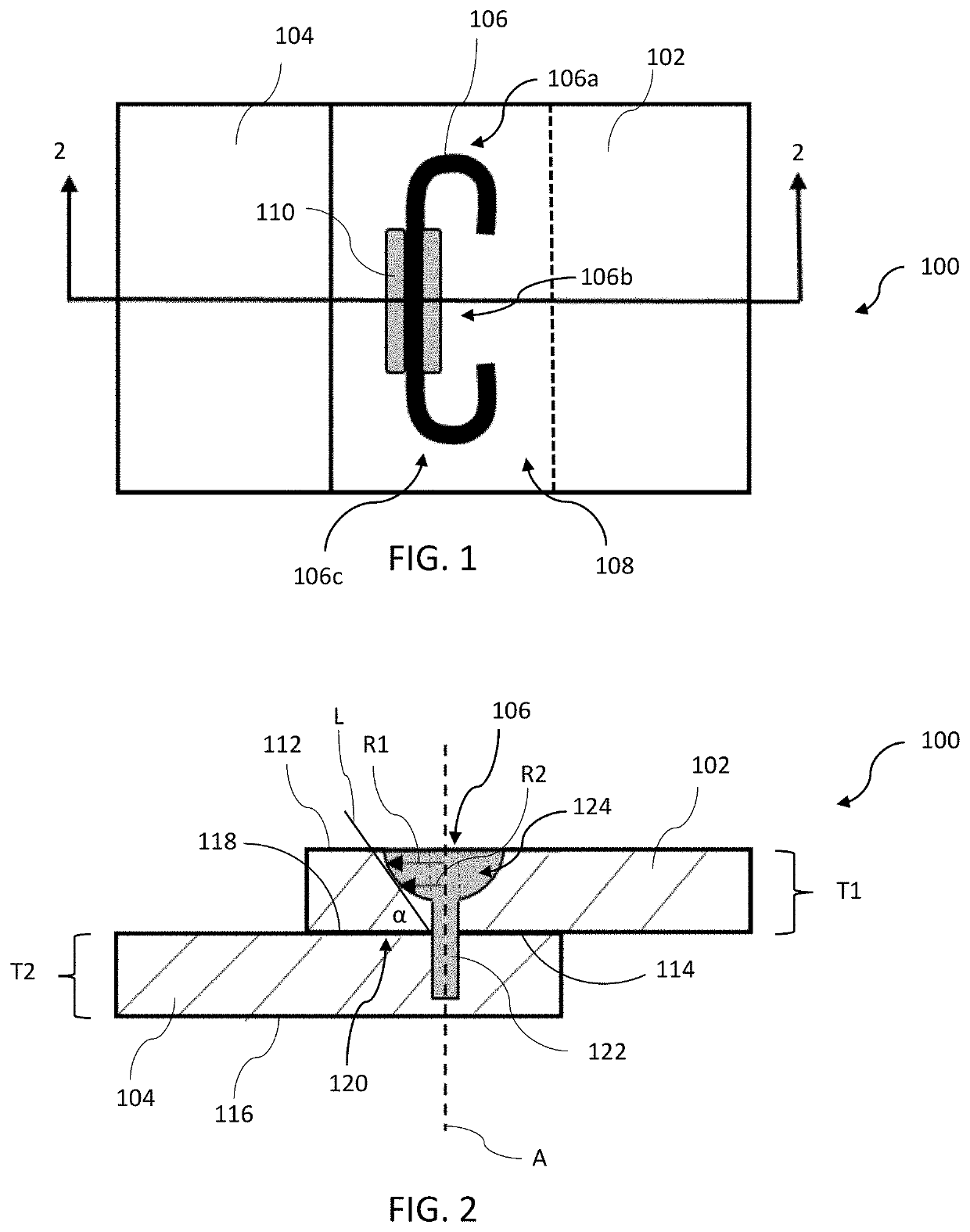
[0042]FIG. 1 shows a top view of a laser welded assembly 100 having a first work piece 102 in overlapping contact with a second work piece 104 and a laser weld 106 in an overlapping region 108 joining the first work piece 102 to the second work piece 104. The first and second work pieces 102 and 104 may be comprised of a wide variety of steels ...


PUM

PropertyMeasurementUnit
Angleaaaaaaaaaa
Angleaaaaaaaaaa
Angleaaaaaaaaaa

Abstract

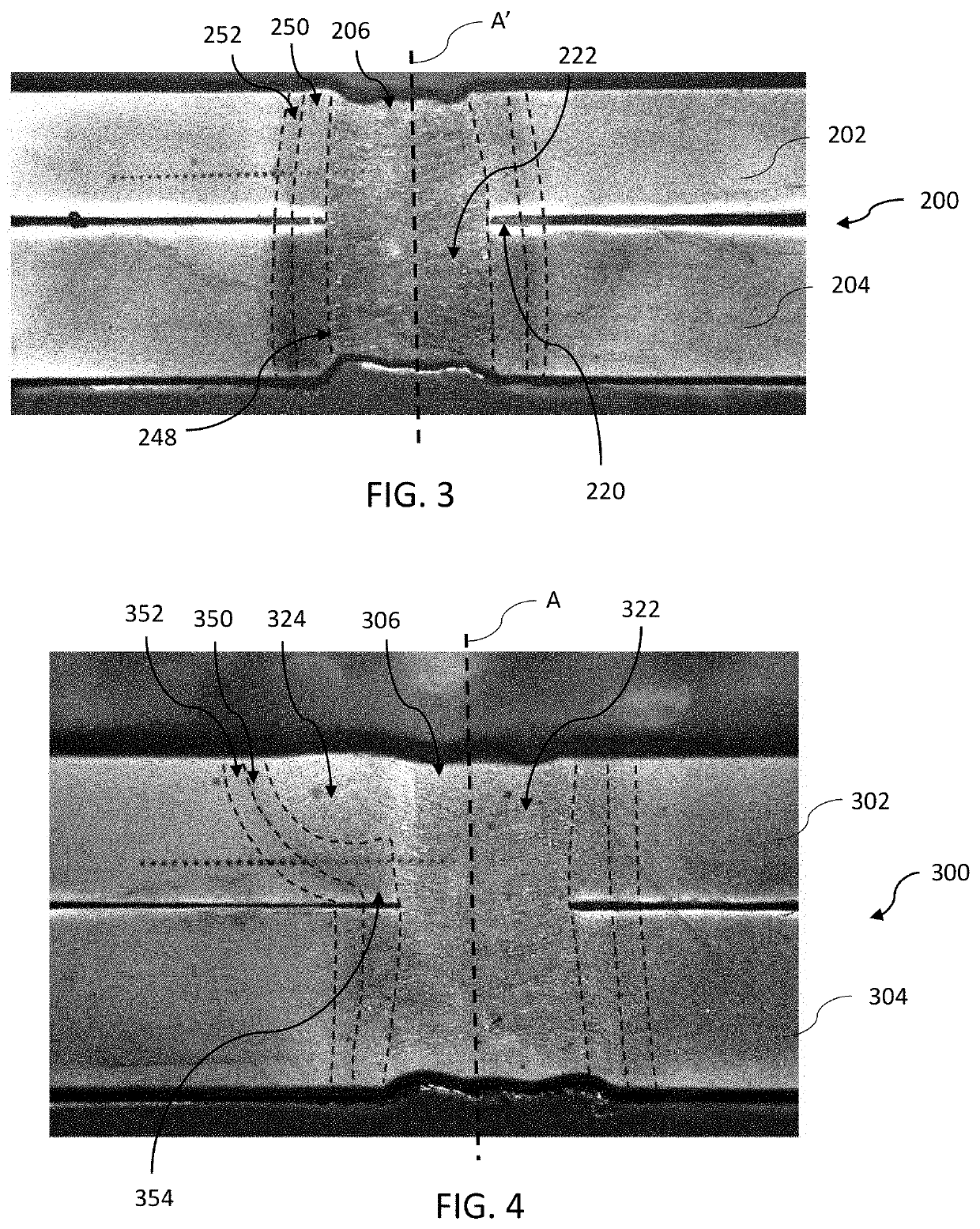
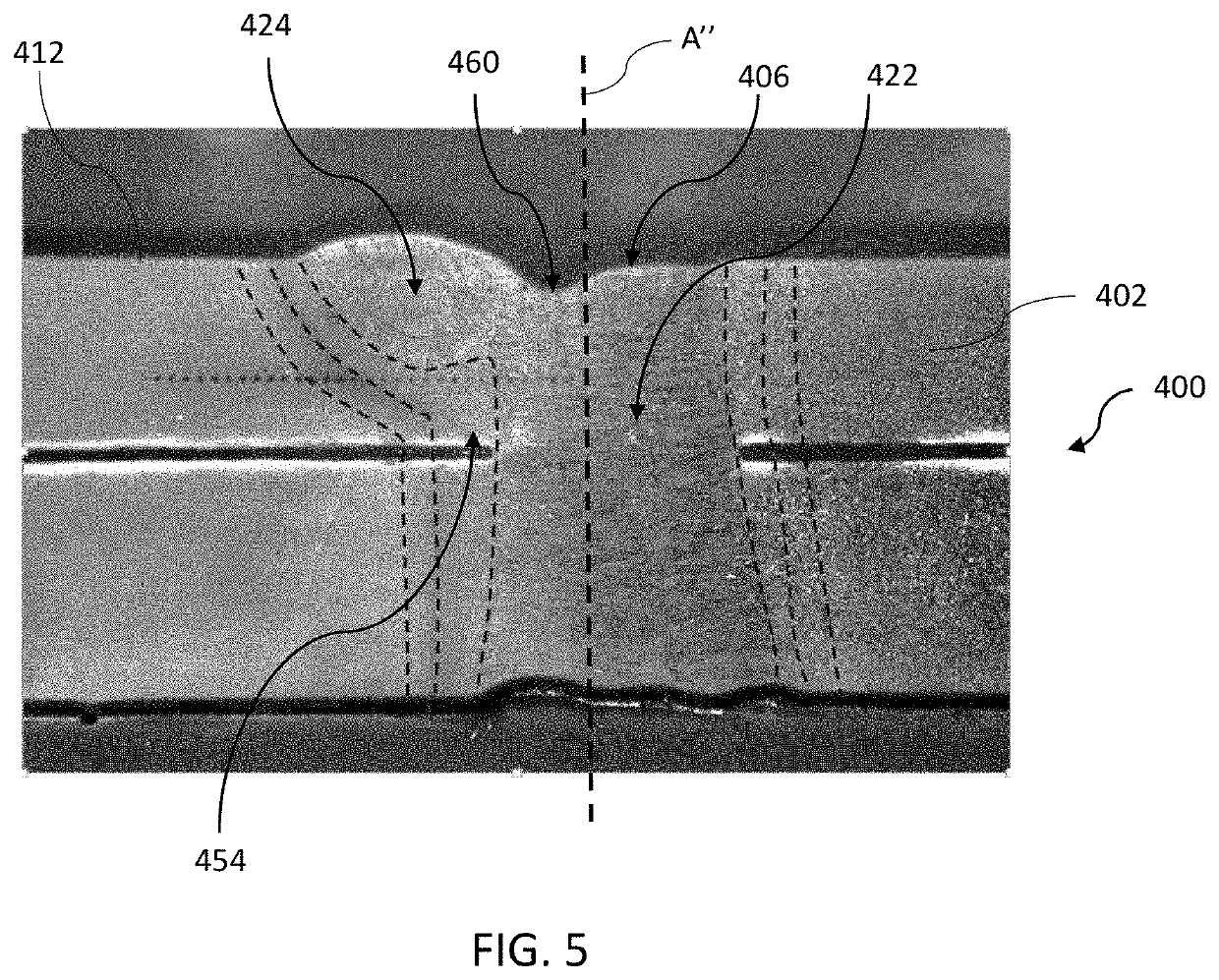
A laser welded assembly and method of making. The laser welded assembly includes a first work piece having a thickness (T1) defined between an external surface and a faying surface; a second work piece having a thickness (T2) defined between an external surface and a faying surface of the second work piece; a weld seam having a core fusion zone extending from the external surface of the first work piece through the faying interface and at least partially into the thickness (T2) of the second work piece; and a protruding fusion zone extending laterally from the core fusion zone adjacent to the external surface of the first work piece. The protruding fusion zone may be formed by post-heating or concurrently with the core fusion zone.

Description

INTRODUCTION[0001]The present disclosure relates to a laser welded assembly, more particularly to laser welded assembly having a heat affected zone reinforcement and a method of making the same.[0002]Automotive body components such as quarter panels, door assemblies, underbody panel members, seat frames, and the likes, are typically assembled by overlapping two or more metal panel members, also referred to as metal work pieces, in which the overlapped portions of the metal panel members are joined by fusion welding, such as resistance spot and conventional arc welding. Recently, laser welding has been adopted as a replacement method for conventional resistance spot and conventional arc welding.[0003]Laser welding is a metal joining process in which a laser beam is directed at a surface of a stacked or overlapping assembly of metal panel members to provide a concentrated heat source capable of effectuating a joint in fusing the metal panel members together. Laser welding uses energy ...

Claims


Application Information

Patent Timeline
IPC IPC(8): B23K26/24B23K26/70
CPCB23K26/24B23K2101/006B23K26/70B23K26/0006B23K26/244
Inventor CHEN, NANNANSOLOMON, JOSHUA L.WANG, HUI-PINGWAN, ZIXUANCARLSON, BLAIR E.TORRES GUZMAN, PAULINA G.
Owner GM GLOBAL TECH OPERATIONS LLC
Learn More