Mounting structure and manufacturing method of mounting structure

a manufacturing method and mounting structure technology, applied in the direction of printed circuit non-printed electric components association, instruments, etc., can solve the problems of large non-flexible region, large non-flexible region, and non-flexible connection unit between non-flexible electronic components or modules using glass epoxy substrates, etc., to achieve the effect of increasing rigidity

Active Publication Date: 2022-03-24
NEC CORP
View PDF3 Cites 0 Cited by
  • Summary
  • Abstract
  • Description
  • Claims
  • Application Information

AI Technical Summary

Benefits of technology

The patent describes a structure that protects a flexible wiring board from deformation and damage when connected to a non-flexible component. This is achieved through the use of a reinforcing material that increases rigidity and prevents cracks and fractures from occurring in the connection unit and the protection resin. The reinforcing material can be a plate, film, or tape shape and is added to the flexible wiring board to reinforce it and ensure its stability during use. The technical effect of this structure is to provide a reliable and durable connection between flexible and non-flexible components.

Problems solved by technology

In contrast, an electronic component such as a semiconductor chip, an electronic module using a glass epoxy substrate, and the like are non-flexible.
A connection unit between such a non-flexible electronic component or module and a flexible substrate is non-flexible and therefore is broken when being deformed.
However, in the technique in Japanese Unexamined Patent Application Publication No. 2019-197313, a problem that a non-flexible region becomes large is produced.
According to the technique, a frame-shaped reinforcing unit that surrounds a region wider than a component is provided and therefore, flexibility of that portion is lost.
However, for example, in a wearable device, when a non-flexible region is large, a wearer may feel a sense of discomfort.
Therefore, a non-flexible region is desirably small.
In Japanese Unexamined Patent Application Publication No. 2008-258497, a reinforcing plate wider than a region where a component is disposed is used and therefore, flexibility of that portion is lost.
Therefore, similarly to Japanese Unexamined Patent Application Publication No. 2019-197313, a problem that a non-flexible region becomes large is produced.

Method used


Image

  • Mounting structure and manufacturing method of mounting structure
  • Mounting structure and manufacturing method of mounting structure
  • Mounting structure and manufacturing method of mounting structure

Examples


first example embodiment

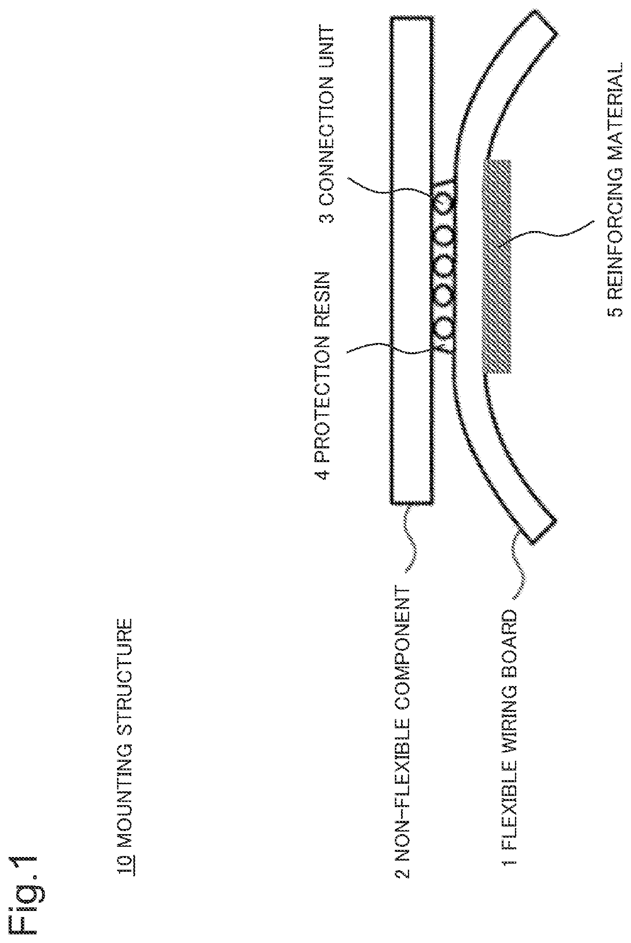
[0025]FIG. 1 is a cross-sectional diagram illustrating a mounting structure 10 according to the present example embodiment. The mounting structure 10 includes a flexible wiring board 1, a non-flexible component 2, and a connection unit 3 that is provided in a region smaller than a bottom face of the non-flexible component 2 and connects the flexible wiring board 1 and the non-flexible component 2. Further, the mounting structure 10 includes, other than the connection unit 3, a protection resin 4 that seals the connection unit 3 in such a way that the flexible wiring board 1 and the non-flexible component 2 are separable from each other. The protection resin 4 covers only a region where the connection unit 3 is provided. A reinforcing material 5 is added to a face of the flexible wiring board 1, the face which is on an opposite side to the connection unit 3. The reinforcing material 5 covers a region that includes an entire region where the connection unit 3 is provided and is narrow...

second example embodiment

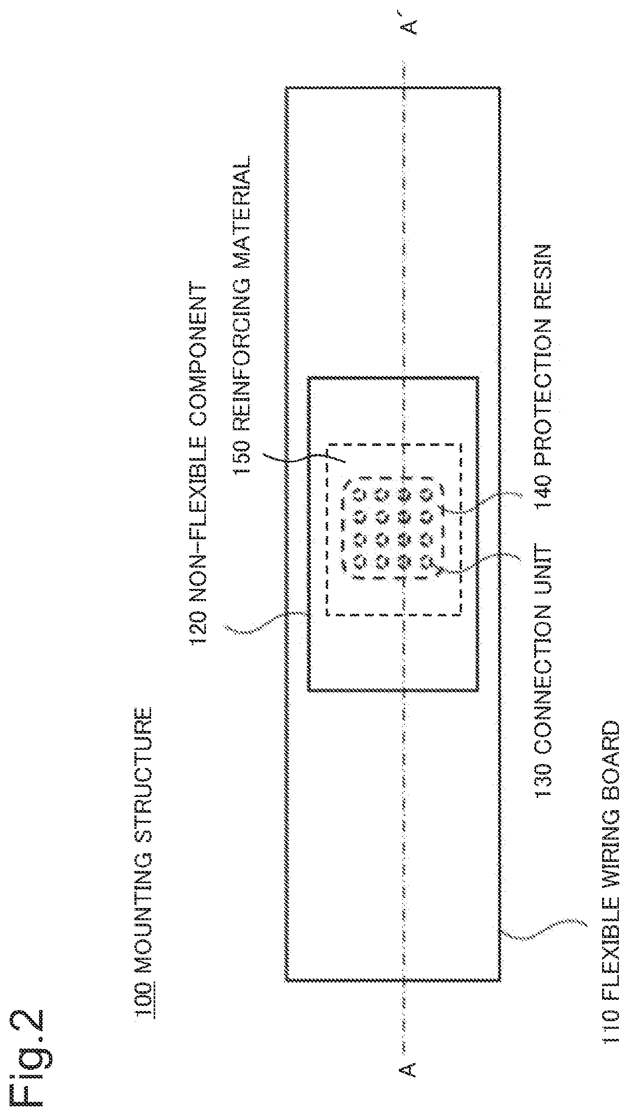
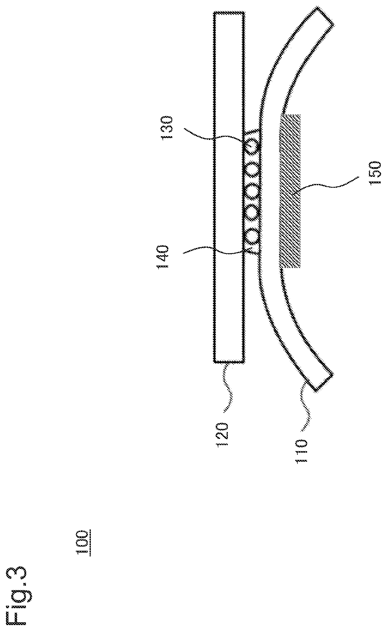
[0027]According to the present example embodiment, a specific configuration of a mounting structure employing the first example embodiment as a basis configuration is described. FIG. 2 is a plan view illustrating a mounting structure 100 according to the present example embodiment. The mounting structure 100 includes a flexible wiring board 110 and a non-flexible component 120. On a bottom face of the non-flexible component 120 (a face opposite to the flexible wiring board 110), a connection unit 130 that connects the flexible wiring board 110 and the non-flexible component 120 is provided in a region narrower than the bottom face. A protection resin 140 is provided in such a way as to cover only a region where the connection unit 130 exists. A reinforcing material 150 is added to a face of the flexible wiring board 110, the face which is on an opposite side to the connection unit 130. The reinforcing material 150 covers a region that includes a region where the connection unit 130 ...

third example embodiment

[0037]According to the present example embodiment, a configuration in which stress concentration in an end of a reinforcing material 150 is relaxed is described. When stress is concentrated in an end of the reinforcing material 150, a flexible wiring board 110 is bent, and as a result, a substrate may be broken and wiring may be disconnected. FIG. 8 is a plan view illustrating a mounting structure 101 according to the present example embodiment, and FIG. 9 is a cross-sectional diagram in a line of B-B′ of FIG. 8.

[0038]The mounting structure 101 includes, in addition to the mounting structure 100 according to the second example embodiment, a low-elasticity resin 160 in a periphery of a protection resin 140. The low-elasticity resin 160 is provided in such a way as to overlap an end of the reinforcing material 150. Low elasticity referred to herein indicates that the elasticity is lower than the protection resin 140. When, for example, a force of pulling down an end of the flexible wi...


PUM


Abstract

To provide a mounting structure in which a connection unit is protected and a non-flexible region is small, the mounting structure includes a flexible wiring board, a non-flexible component, and a connection unit provided in a region smaller than a bottom face of the non-flexible component and connecting the flexible wiring board and the non-flexible component. The mounting structure includes a protection resin sealing the connection unit in such a way that the flexible wiring board and the non-flexible component are separable. The protection resin covers only a region where the connection unit is provided. To a face of the flexible wiring board, being on an opposite side to the connection unit, a reinforcing material is added. The reinforcing material covers a region where the connection unit is provided and being narrower than the bottom face of the non-flexible component.

Description

[0001]This application is based upon and claims the benefit of priority from Japanese Patent Application No. 2020-159316, filed on Sep. 24, 2020, the disclosure of which is incorporated herein in its entirety by reference.TECHNICAL FIELD[0002]The present invention relates to a mounting structure and a manufacturing method of a mounting structure.BACKGROUND ART[0003]In recent years, as in a wearable device to be worn and used by a person, and the like, an electronic device has been actively mounted on a curved face. For a device mounted on a curved face in this manner, it is necessary to mount an electronic component and a module on a flexible substrate such as a flexible printed wiring board. In contrast, an electronic component such as a semiconductor chip, an electronic module using a glass epoxy substrate, and the like are non-flexible. A connection unit between such a non-flexible electronic component or module and a flexible substrate is non-flexible and therefore is broken whe...

Claims


Application Information

Patent Timeline
Patent Type & Authority Applications(United States)
IPC IPC(8): H05K1/18H05K1/02H05K3/36G06F1/16
CPCH05K1/189G06F1/163H05K3/361H05K1/0281H05K1/181H05K3/303H05K3/305H05K2201/2009H05K3/3436
Inventor OTSUKA, KYOKO
Owner NEC CORP
Why Eureka
Try Eureka