Behind casing cementing tool

a cementing tool and casing technology, applied in the direction of sealing/packing, earthwork drilling and mining, and wellbore/well accessories, etc., can solve the problems of tool jamming in the casing, inability to achieve effective cement bond, and high cost of remedying, so as to reduce the diameter of the tool is reduced, and the path is small.

Pending Publication Date: 2022-02-24
CONOCOPHILLIPS CO
View PDF6 Cites 0 Cited by
  • Summary
  • Abstract
  • Description
  • Claims
  • Application Information

AI Technical Summary

Benefits of technology

[0015]There is therefore a conflict between making the outer diameter of cementing tool as large as possible, whilst keeping the risk of stuck pipe to an acceptable level.
[0016]A potential problem with using a relatively large diameter cementing tool arises when the casing is deformed at some point above the region to be cemented, thereby creating in effect a smaller pathway for the tool. Cause for such a restriction can be geological events like subsidence or effective horizontal stress larger than the collapse capacity of the casing. There may be other reasons why it is required to be able to pass the tool through a narrower section of tubing or casing than the section to be treated by the tool (typically referred to as a patch), for example if the tool is to be passed through a section of concentric smaller diameter tubing above a larger diameter region for cementing (typically established by window milling).
[0017]The cementing tool is, in essence, a hollow cylinder with apertures in it which function as nozzles for creating outwardly directed jets of cement when pressurized cement is passed into the tool. The tool is run on drillstring and is rotated as well as being moved axially such that the jets of cement create pulses of pressure in the casing which are transmitted through perforations in the casing and energize the fluid in the outer annulus, thereby displacing it to cement.
[0018]The inventors have conceived an improved design of cementing tool which has a variable outer diameter, such that it can be passed down the casing in a narrow configuration and, when the time comes for cement to be injected, its diameter can be increased. In this way, the tool may be passed through restrictions in the casing etc, and if stuck pipe should occur during a cementing operation, the diameter of the tool may be reduced to free the tool.

Problems solved by technology

Displacement of the fluid is important because, if the cement mixes substantially with wash fluid then an effective cement bond may not be achieved.
This can result in the tool becoming jammed in the casing (so called “stuck pipe”) and can be expensive to remedy.
There is therefore a conflict between making the outer diameter of cementing tool as large as possible, whilst keeping the risk of stuck pipe to an acceptable level.

Method used


Image

  • Behind casing cementing tool
  • Behind casing cementing tool

Examples


Embodiment Construction

[0029]Turning now to the detailed description of the preferred arrangement or arrangements of the present invention, it should be understood that the inventive features and concepts may be manifested in other arrangements and that the scope of the invention is not limited to the embodiments described or illustrated. The scope of the invention is intended only to be limited by the scope of the claims that follow.

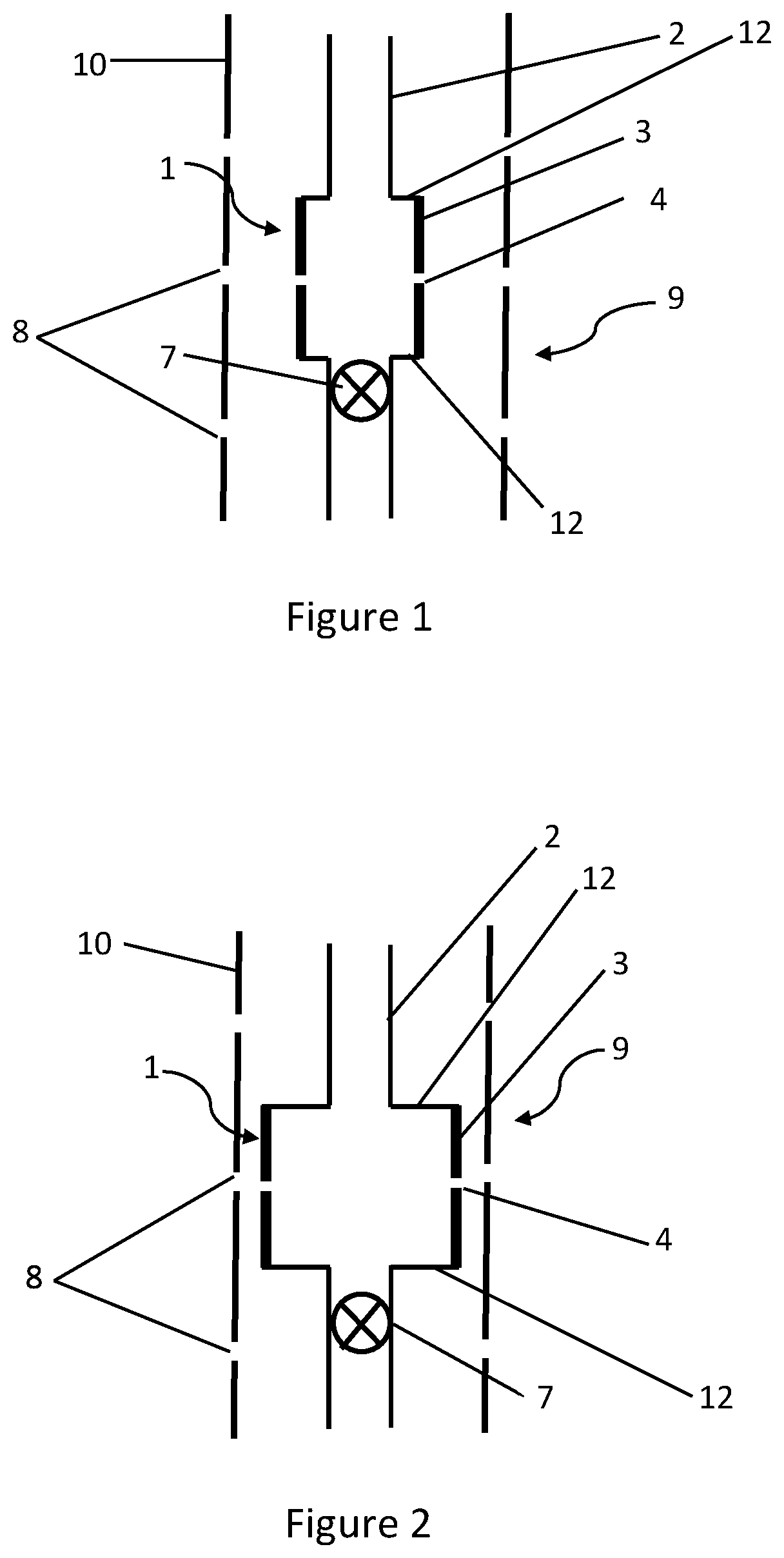
[0030]Referring firstly to FIG. 1, a cementing tool 1 is shown in highly schematic form. The aspect ratio of the real tool would be considerably longer, but it is illustrated in this way for clarity. The tool 1 comprises in essence a hollow cylindrical shape with two apertures 4 in the cylindrical wall 3. These apertures 4 are lined with a wear resistant material to avoid them being worn away when cement is jetted through them—this is not shown in the drawing but is in itself conventional.

[0031]The tool 1 is attached to drill string 2 on which it would be run into a well. Ben...


PUM


Abstract

The invention relates to a cementing tool for use in oil and gas well decommissioning operations, in particular so called perforate, wash and cement procedures. The tool (1) is designed for running in a well on drill string and for jetting cement through previously formed perforations in the casing (10) to fill the outer annulus (9) with cement. The tool (1) has a cylindrical wall (3) which is formed from steel (11) and elastomeric (5) elements, whereby it is expandable between a first diameter in which it may be run down the well and a second, larger diameter deployed during cementing operations. (FIG. 2).

Description

CROSS-REFERENCE TO RELATED APPLICATIONS[0001]This application is a non-provisional application which claims benefit under 35 USC § 119(e) to U.S. Provisional Application Ser. No. 63 / 067,599 filed Aug. 19, 2020, entitled “Jet-Type Perforation-Wash-Cement Parameterization,” U.S. Provisional Application Ser. No. 63 / 112,427 filed Nov. 11, 2020, entitled “Behind Casing Wash and Cement,” U.S. Provisional Application Ser. No. 63 / 112,440 filed Nov. 11, 2020, entitled “Behind Casing Cementing Tool” and U.S. Provisional Application Ser. No. 63 / 112,448 filed Nov. 11, 2020, entitled “Setting a Cement Plug”, each of which is incorporated herein in its entirety.STATEMENT REGARDING FEDERALLY SPONSORED RESEARCH[0002]None.FIELD OF THE INVENTION[0003]This invention relates to the process of cementing behind the casing of a well, for example in a so-called perf, wash cement well decommissioning operation.BACKGROUND OF THE INVENTION[0004]In a process for placing cement in the annulus of a well, normall...

Claims


Application Information

Patent Timeline
Patent Type & Authority Applications(United States)
IPC IPC(8): E21B33/14
CPCE21B33/14E21B41/0078E21B37/00E21B33/13
Inventor HOVDA, LARSSTEVENS, JAMES C.MUELLER, DANPHADKE, AMALGONUGUNTLA, PRAVEEN
Owner CONOCOPHILLIPS CO
Why Eureka
Try Eureka