Transmission

a transmission and gear technology, applied in the direction of transmission elements, gearboxes, toothed gearings, etc., can solve the problem of increasing the size of the transmission

Active Publication Date: 2018-07-31
JAGUAR LAND ROVER LTD
View PDF15 Cites 0 Cited by
  • Summary
  • Abstract
  • Description
  • Claims
  • Application Information

AI Technical Summary

Benefits of technology

[0010]The low forward speed ratio provided via the sleeve requires a plurality of additional gear wheels in the gear wheel train. However by arranging this ratio as an off-highway ratio, the risk of additional noise may be acceptable.

Problems solved by technology

Inevitably, these additional speed ratios tend to increase the size of the transmission, which is problematic for vehicle designers where the available space envelope is restricted.

Method used


Image

  • Transmission
  • Transmission
  • Transmission

Examples


Embodiment Construction

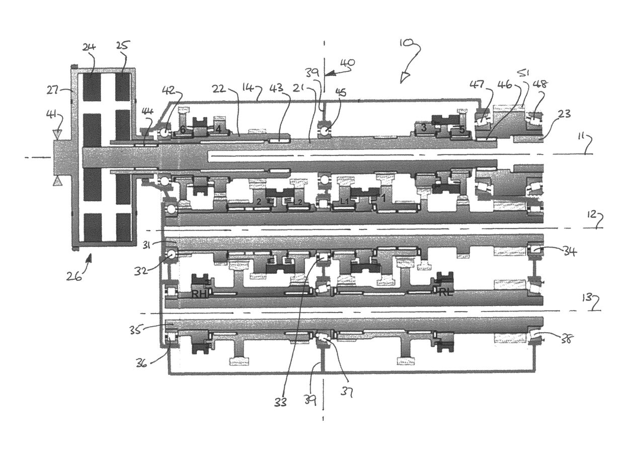
[0027]A gear transmission 10 according to an embodiment of the invention is illustrated in FIG. 1, and comprises a plurality of shafts rotatable about three parallel axes 11, 12, 13 within a casing 14 to define a north / south (longitudinal) arrangement. The illustrated embodiment of the invention is a dual clutch transmission (DCT) but as will be described below, a conventional single clutch variant is also possible.

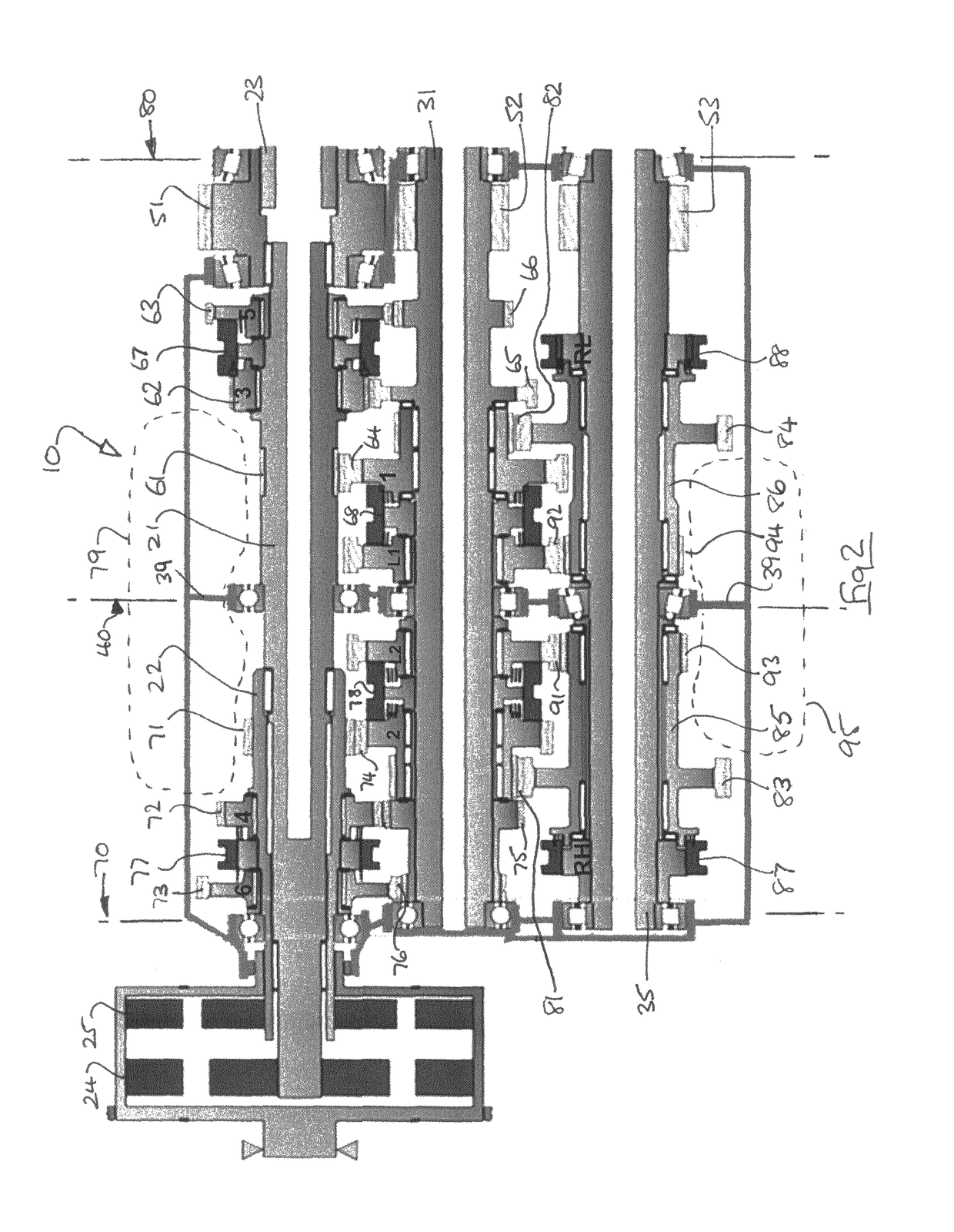
[0028]The transmission of FIG. 1 is developed so as to be illustrated in a single plane for the purposes of description. A practical embodiment has the axes arranged in triangular form, as will also become apparent, and is illustrated in FIG. 3.

[0029]The uppermost axis 11 (as viewed) comprises an input / output axis on which is rotatable an inner input shaft 21, an outer input shaft 22 and an output shaft 23. The input shafts 21, 22 are driven via respective driven plates 24, 25 of a dual clutch 26, each driven plate being engageable on demand with a driving member 27 coupl...


PUM


Abstract

A constant mesh gear transmission has an input shaft (21, 22), two layshafts (31, 35) and an output shaft (23). Gear wheels are selectively connectable to shafts to provide forward and reverse speed ratios. Reverse speed ratio is via a sleeve (85, 86) of a reverse layshaft (35). The sleeve can also re-circulate torque to a forward layshaft (31) to provide an additional low forward speed ratio. Two sleeves and two additional low forward speed ratios are disclosed.

Description

TECHNICAL FIELD[0001]The present invention relates to a gear transmission and particularly, but not exclusively, to a transmission having a plurality of selectable speed ratios provided by respective trains of gear wheels. Aspects of the invention relate to a gearbox, to a powertrain and to a vehicle.BACKGROUND[0002]Gear transmissions are typically used in motor vehicles, and multiple speed ratios allow the engine characteristics to be best matched to the required gradient launch, acceleration, top speed, fuel economy and other well understood factors. Gear pairs are typically in constant mesh, and are engaged and disengaged by synchromesh mechanisms which incorporate dog clutches. Manual selection of the required speed ratio is common, but some gear transmission variants have automated or assisted selection, or have fully automatic speed ratio selection.[0003]In order to achieve good acceleration and fuel economy, the number of speed ratios have increased in recent years, and for s...

Claims


Application Information

Patent Timeline
Patent Type & Authority Patents(United States)
IPC IPC(8): F16H3/08F16H3/097B60K17/08F16H3/00F16H3/093F16H57/021F16H57/02B60K17/346
CPCF16H3/093B60K17/08F16H3/006F16H3/097F16H57/021B60K17/346F16H2200/0086F16H2003/0931F16H2003/0933F16H2057/0216F16H2057/02047F16H2200/006F16H2003/0822
Inventor HOSE, MARKUSOSBORN, RUSSELLHYDE, FREDHOLE, MATT
Owner JAGUAR LAND ROVER LTD
Why Eureka
Try Eureka